
An antifreeze differential pressure flowmeter

A technology of differential pressure flowmeter and flow totalizer, which is applied in the field of flowmeters, and can solve problems such as the failure of fluid medium to conduct pressure, fluid solidification, and inability to measure fluid flow in pipelines.

Active Publication Date: 2018-02-06
LIAONING BITOBAR TECH CO LTD
View PDF6 Cites 0 Cited by
  • Summary
  • Abstract
  • Description
  • Claims
  • Application Information

AI Technical Summary

Problems solved by technology

[0003] For the Bitobar flowmeter in the prior art, part of the pressure guide tube of the Bitobar sensor will be placed outside the pipeline during installation and use. If the external ambient temperature is low, the fluid in the pressure guide tube may solidify, resulting in The fluid medium in the pressure guide tube cannot guide the pressure, resulting in the inability to measure the fluid flow in the pipeline

Method used


Image

  • An antifreeze differential pressure flowmeter

Examples


Embodiment Construction

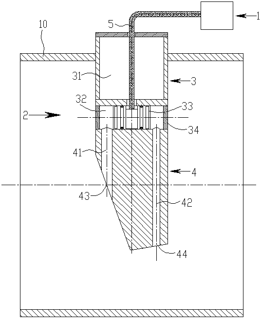
[0009] see figure 1 , figure 1 It shows a schematic cross-sectional structural view of an antifreeze differential pressure flowmeter of the present invention installed on the pipeline 10 . The antifreeze differential pressure flowmeter of the present invention has a flow totalizer 1 and a pressure taking head 2 of a Bitobar flow sensor, and the pressure taking head 2 of the Bitobar flow sensor includes a cylindrical joint 3 in the upper section and a pressure taking head in the lower section Body 4, pressure taking head body 4 is provided with a total pressure channel 41 and a static pressure channel 42 whose axis is parallel to the axis of the pressure taking head and located in the same plane. The bottom of the total pressure channel 41 has a total pressure hole 43 and a static pressure channel 42 The bottom of the bottom has a static pressure hole 44, the upper part of the cylindrical joint 3 has an axial cylindrical chamber 31, and its lower part is provided with a differ...


PUM


Abstract

The invention discloses an antifreeze differential pressure flowmeter, which has a flow totalizer and a Bitoba flow sensor to take a pressure head, the upper part of the cylindrical joint of the pressure head has a cylindrical chamber, and the lower part is provided with a differential pressure switch device; the differential pressure switch device includes a radial cylindrical hole that runs through the lower part of the cylindrical joint. The axes of the pressure channels are perpendicular to each other, and the inner diameters of the cylindrical holes are respectively larger than the inner diameters of the total pressure channel and the static pressure channel. They are located approximately in the middle of the axis of the cylindrical hole and are sealed with a differential pressure sensitive diaphragm. The total pressure channel and the static pressure channel The upper ports of the differential pressure sensitive diaphragm are respectively located on both sides of the differential pressure sensitive diaphragm, and the two ends of the cylindrical hole are sealed with side end covers. The signal output end of the differential pressure sensitive diaphragm is connected with a signal cable, and the signal cable passes through the The cylindrical chamber is connected with the signal input end of the flow totalizer. When the invention measures the fluid flow in the pipeline, it is not affected by the ambient temperature outside the pipeline.

Description

technical field [0001] The invention relates to a flowmeter for measuring fluid flow in a pipeline, in particular to an antifreeze differential pressure flowmeter. Background technique [0002] At present, there are many types of flow measuring devices for measuring the flow of fluid in pipelines. Bitoba flowmeters are widely used to measure the flow of fluid in pipelines due to their simple structure, convenient installation and relatively high measurement accuracy. The Bitobar flowmeter is mainly composed of a Bitobar sensor, a differential pressure transmitter and a flow totalizer. The differential pressure transmitter converts the full pressure and static pressure signals of the fluid in the pipeline transmitted by the Bitobar sensor into The 20mA standard current signal is sent to the flow totalizer, and the flow totalizer finally calculates the flow of the fluid flowing through the pipeline according to the principle of fluid mechanics. [0003] For the Bitobar flowme...

Claims


Application Information

Patent Timeline
Patent Type & Authority Patents(China)
IPC IPC(8): G01F1/46
Inventor 王忠辉
Owner LIAONING BITOBAR TECH CO LTD
Learn More