Motor driving system current sensor fault diagnosis method

A technology of motor drive system and current sensor, which is applied in the direction of instruments, measuring electric variables, measuring devices, etc., can solve the problems of cost increase, achieve cost saving, and realize the effect of torque safety control

Active Publication Date: 2015-07-22
UNITED AUTOMOTIVE ELECTRONICS SYST
View PDF4 Cites 6 Cited by
  • Summary
  • Abstract
  • Description
  • Claims
  • Application Information

AI Technical Summary

Problems solved by technology

Although this scheme improves the torque safety level, but because three current sensors are required, the cost increases a lot

Method used


Image

  • Motor driving system current sensor fault diagnosis method
  • Motor driving system current sensor fault diagnosis method
  • Motor driving system current sensor fault diagnosis method

Examples


Embodiment 1

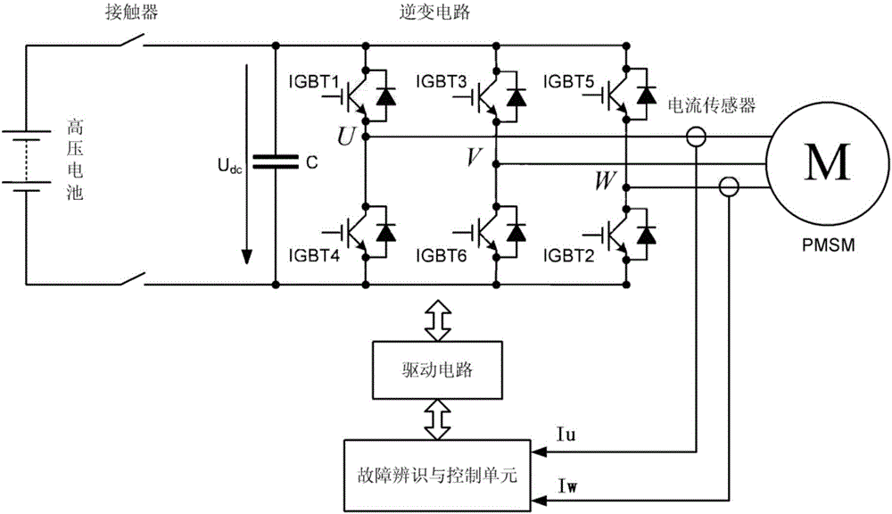
[0020] Motor drive systems such as figure 1 As shown, it includes a motor, a motor controller, a fault identification and control unit, a drive circuit, and two current sensors. The two current sensors detect the current of any two phases of U, V, and W of the three-phase motor. The fault identification and The control unit performs fault diagnosis on the current sensor itself based on the current detection values ​​of the two current sensors.

[0021] Motor drive system current sensor fault diagnosis method:

[0022] Use the first current sensor and the second current sensor to detect the current of any two phases of the three-phase motor respectively;

[0023] Sampling the phase current detected by the first current sensor and the phase current detected by the second current sensor, the number of sampling points in one phase current cycle is N;

[0024] Calculate the N phase current amplitudes in a phase current cycle, In the formula, A(M) is the Mth phase current amplit...

Embodiment 2

[0031] Based on the motor drive system current sensor fault diagnosis method in Embodiment 1, a phase current starting from the peak time (the peak time can be selected as the positive peak value or the negative peak value) of the phase current detected by the current sensor is also calculated. Each accumulated current value within the current cycle and calculate the sine degree, If the N sine degrees in the phase current cycle are not constant (that is, more than P sine degrees exceed the sine degree threshold range, P is a positive integer less than N, and the sine degree threshold range is obtained by matching), then judge the phase The current is non-sinusoidal, and the current sensor has a serious or precision failure; I' M is the cumulative current value up to the Mth sampling point in the phase current cycle, I M is the Mth sampling value in the phase current cycle, I k is the kth sampling value in this phase current cycle, I 1 is the current sampling value at the p...

Embodiment 3

[0049] Based on the motor drive system current sensor fault diagnosis method of Embodiment 2, within a phase current cycle, if the sampled value of the phase current detected by a current sensor is always a constant value, such as: ±Imax, or between ±Imax A certain constant value of , it is judged that the current sensor is unreasonable, and the current sensor has a serious fault.

[0050] It should be noted that in special working conditions, such as locked rotor or large-scale fluctuation of torque command, the accuracy fault diagnosis of the current sensor can be disabled first (that is, the balance and sine degree diagnosis should be disabled), and only for serious faults of a single current sensor Carry out diagnosis (that is, only open the rationality diagnosis of the single-phase current in Embodiment 3, and the locked-rotor working condition can be known from the motor position sensor), so as to avoid false alarms of diagnostic faults. Due to the limited duration of th...


PUM


Abstract

The invention discloses a motor driving system current sensor fault diagnosis method comprising the following steps: respectively detecting the current of any two phases of a three-phase motor by two current sensors, and sampling the phase current detected by the first current sensor and the phase current detected by the second current sensor, wherein the number of sampling points in a phase current period is N; calculating the phase current amplitude A(M) (the formula is shown in the description) in a phase current period; and judging that the phase current is unbalanced and there is a serious or precision fault in the current sensors if the phase current amplitude in the phase current period exceeds a phase balance threshold range for multiple times. According to the motor driving system current sensor fault diagnosis method of the invention, fault diagnosis of a current sensor can be realized by two current sensors, and the cost is saved.

Description

technical field [0001] The invention relates to motor technology, in particular to a fault diagnosis method for a current sensor of a motor drive system. Background technique [0002] Electric (pure electric or hybrid) vehicle motor drive system mainly includes motor, motor controller and related control circuits. Electric vehicle torque control is realized by current closed-loop control, so the failure of current sensor will have a direct impact on torque control. Current sensor faults are mainly divided into two categories: serious faults and precision faults. Serious faults mainly include: current sensor short circuit, open circuit, constant value, etc.; and precision faults include: current sensor bias, drift, proportional faults, etc. [0003] Since motor current is directly related to torque safety, current sensors for electric vehicles require high diagnostic coverage. In order to ensure high-level torque safety requirements, the existing electric vehicle motor dri...

Claims


Application Information

Patent Timeline
Patent Type & Authority Applications(China)
IPC IPC(8): G01R35/00
Inventor 吴璐璐何海
Owner UNITED AUTOMOTIVE ELECTRONICS SYST
Why Eureka
Try Eureka