Liquid crystal display panel and liquid crystal display device

A liquid crystal display panel and substrate technology, applied in nonlinear optics, instruments, optics, etc., can solve problems such as leakage, uneven display of liquid crystal display panels, etc., and achieve the effect of avoiding leakage

Active Publication Date: 2015-07-22
KUSN INFOVISION OPTOELECTRONICS
View PDF6 Cites 2 Cited by
  • Summary
  • Abstract
  • Description
  • Claims
  • Application Information

AI Technical Summary

Problems solved by technology

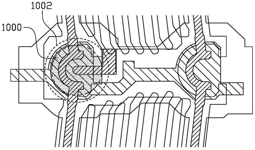
like figure 2 As shown, in order to prevent the spacers from affecting the aperture ratio of the liquid crystal display panel, the spacers 1000 are uniformly distributed over the entire TFT 1002 of the plurality of pixel units, but the spacers arranged in the above method, when there is pressure perpendicular to the liquid crystal display panel , will cause the channel region of the TFT to be pressured through the spacer, resulting in leakage, which will cause the problem of uneven display of the liquid crystal display panel

Method used


Image

  • Liquid crystal display panel and liquid crystal display device
  • Liquid crystal display panel and liquid crystal display device
  • Liquid crystal display panel and liquid crystal display device

Examples


Embodiment Construction

[0027] In order to further explain the technical means and effects of the present invention to achieve the intended purpose of the invention, the specific implementation methods, methods, and steps of the liquid crystal display panel and its forming method proposed according to the present invention will be described below in conjunction with the accompanying drawings and preferred embodiments. , structure, feature and effect, detailed description is as follows.

[0028] The foregoing and other technical contents, features and effects of the present invention will be clearly presented in the following detailed description of preferred embodiments with reference to the drawings. Through the description of specific implementation methods, the technical means and effects of the present invention to achieve the intended purpose can be understood more deeply and specifically, but the attached drawings are only for reference and description, and are not used to explain the present in...


PUM


Abstract

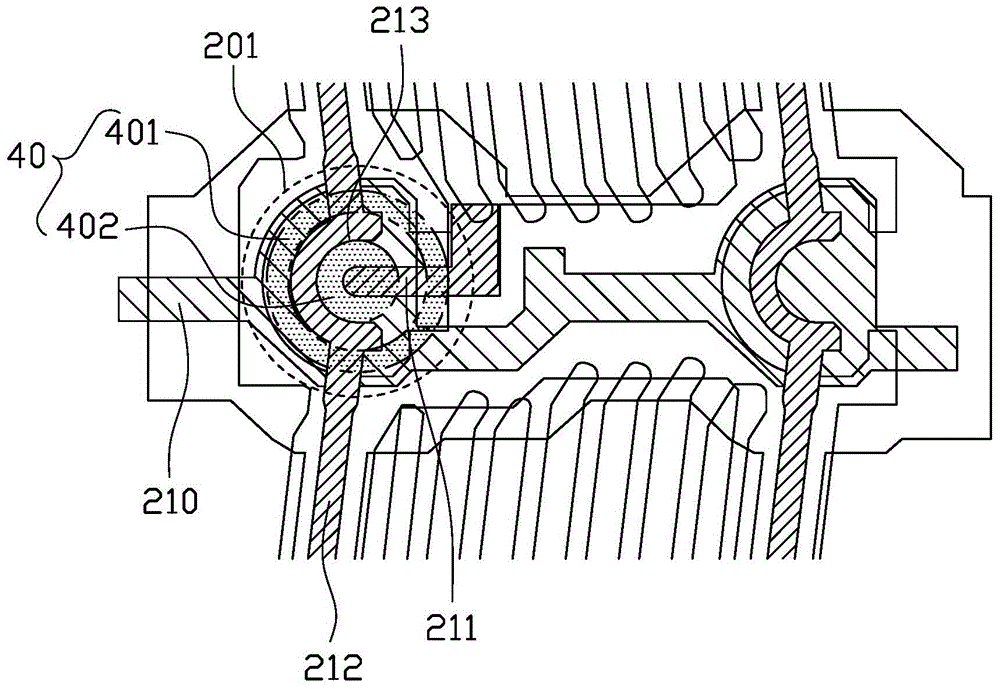
The invention provides a liquid crystal display panel. A plurality of TFTs are arranged on a lower substrate of the liquid crystal display panel. Each TFT comprises a channel region. Partition objects are arranged on the corresponding TFTs respectively. Each partition object comprises a main partition part and an auxiliary partition part. Each main partition part comprises a main partition region and an excavated region which is arranged on the channel region of the corresponding TFT. Each auxiliary partition part is located in the excavated region of the corresponding main partition part. The height, in the perpendicular direction of the lower substrate, of each auxiliary partition part is smaller than the height, in the perpendicular direction of the lower substrate, of the corresponding main partition plate. The invention further provides a formation method of the liquid crystal display panel. According to the liquid crystal display panel and the formation method, the excavated regions of the main partition parts are arranged on the channel regions of the corresponding TFTs, the auxiliary partition parts are located on the excavated regions of the main partition parts, the height, in the perpendicular direction of the lower substrate, of each auxiliary partition plate is smaller than the height, in the perpendicular direction of the lower substrate, of the corresponding main partition plate, when the liquid crystal display panel bears pressure, the main partition regions of the main partition parts bear main pressure, pressure borne by the channel regions of the TFTs becomes smaller, and therefore electric leakage is avoided.

Description

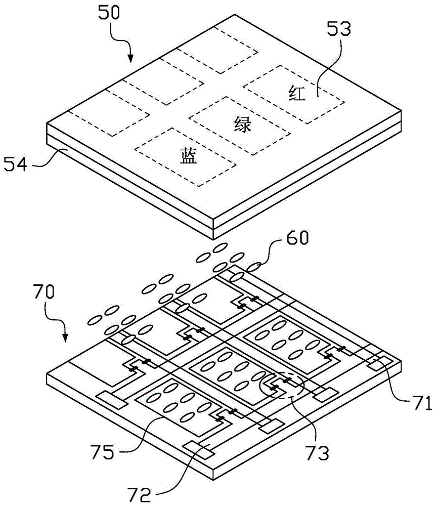
technical field [0001] The invention relates to the technical field of liquid crystal display, in particular to a liquid crystal display panel and a liquid crystal display device. Background technique [0002] The liquid crystal display (Liquid Crystal Display, LCD) has many advantages such as thinness, energy saving, and no radiation, and has gradually replaced the traditional cathode ray tube (CRT) display. Currently, liquid crystal displays are widely used in high-definition digital televisions, desktop computers, personal digital assistants (PDAs), notebook computers, mobile phones, digital cameras and other electronic devices. [0003] Taking a thin film transistor (Thin Film Transistor, TFT) liquid crystal display device as an example, the device includes a liquid crystal display panel and a driving circuit, wherein the liquid crystal display panel includes a TFT array substrate, a color filter substrate arranged opposite to the TFT array substrate, and a The liquid c...

Claims


Application Information

Patent Timeline
IPC IPC(8): G02F1/1339G02F1/1333
CPCG02F1/13394G02F1/13396
Inventor 杜鸣菲陈杰
Owner KUSN INFOVISION OPTOELECTRONICS
Why Eureka
Try Eureka