Modeling method for judging cutting force of orthogonal turn-milling machining end face on basis of boundary conditions

A technology of orthogonal turning and milling and boundary conditions, applied in special data processing applications, instruments, electrical digital data processing, etc., can solve unfavorable problems

Inactive Publication Date: 2015-07-22
BEIHANG UNIV
View PDF5 Cites 16 Cited by
  • Summary
  • Abstract
  • Description
  • Claims
  • Application Information

AI Technical Summary

Problems solved by technology

[0003] The purpose of the present invention is to overcome the shortcomings of the existing technology that are not conducive to computer programming when predicting the cutting force of the face edge in the process of orthogonal turning and milling. The present invention provides a kind of orthogonal turning and milling based on the boundary condition judgment method Modeling Method of Face Cutting Force

Method used


Image

  • Modeling method for judging cutting force of orthogonal turn-milling machining end face on basis of boundary conditions
  • Modeling method for judging cutting force of orthogonal turn-milling machining end face on basis of boundary conditions
  • Modeling method for judging cutting force of orthogonal turn-milling machining end face on basis of boundary conditions

Examples


Embodiment

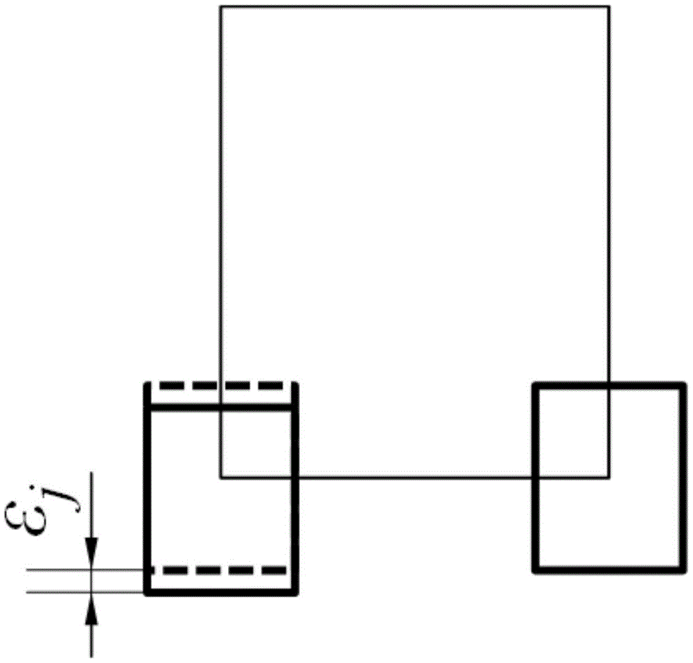
[0059] Orthogonal turning and milling of aluminum alloy 7050 round bars. The diameter of the workpiece is 40mm, and the rotation speed is 10rpm; the diameter of the tool is 16mm, 2 teeth, the rotation speed during processing is 1800rpm, the feed speed along the axial direction of the workpiece is 20mm / min, the processing method is no eccentricity, down milling, and the depth of cut is 2.5mm , taking No. 1 tooth as a reference, the runout of the tooth is 0mm and 0.008mm respectively.

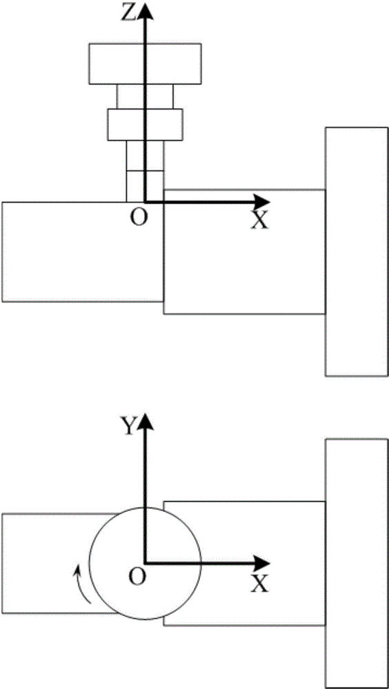
[0060] Step 1: Take the center of the bottom surface of the tool as the origin, take the direction parallel to the workpiece axis as the X-axis, and take the direction of the tool axis as the Z-axis to establish a Cartesian coordinate system, that is, the tool coordinate system, such as figure 1 shown.

[0061] Step 2: Carry out discretization processing on the tool end face edge at an interval of 0.1mm along the radial direction. It can be seen from the cutting parameters that the discretizati...


PUM


Abstract

The invention discloses a modeling method for judging the cutting force of an orthogonal turn-milling machining end face on the basis of boundary conditions. The method includes the five steps of firstly, establishing a tool coordinate system; secondly, dividing the tool end face into a plurality of microelements in the radial direction; thirdly, judging whether the microelements participate in cutting or not through the boundary conditions; fourthly, obtaining thickness of cuttings, and calculating the microelement cutting force on the basis of the thickness; fifthly, adding the cutting force on all the microelements participating in cutting to obtain the total cutting force. By means of the method for judging the cutting state of the microelements through a united boundary condition equation, the disadvantage that in the prior art, when the orthogonal turn-milling machining end face blade cutting force is predicted, the cutting progress needs to be divided into multiple stages to be discussed is avoided; due to the fact that the influences of jumping are taken into consideration, the prediction effect is more accurate. The expression is simple and easy to understand, the complex characteristic angle calculation is omitted, and the modeling method is suitable for development of virtual machining simulation systems and has good application aspects.

Description

technical field [0001] The invention relates to a method for modeling the cutting force of an end face edge in orthogonal turning and milling processing based on boundary condition judgment, and belongs to the field of numerical control processing simulation. Background technique [0002] With the development of advanced manufacturing technology, the combined turning and milling process has gradually become an important means in the field of mechanical processing to deal with rotary parts with complex features. However, the current research on this technology is not enough. In practice, manufacturing engineers rely more on experience or refer to the traditional milling process to select cutting parameters. This method of determining cutting parameters often fails to fully consider the characteristics of the turn-milling composite machining process, which restricts its further performance. Accurate prediction of cutting force can provide an important reference for manufactur...

Claims


Application Information

Patent Timeline
Patent Type & Authority Applications(China)
IPC IPC(8): G06F19/00
Inventor 刘强邱文旺袁松梅李传军
Owner BEIHANG UNIV
Why Eureka
Try Eureka