
Wire twisting mechanism for T1 ring wire winding machine

A technology of winding wires and twisted wires, which is applied in the field of network transformer winding machines, can solve the problems of inconvenient automation, time-consuming and labor-intensive labor costs, etc.

Active Publication Date: 2015-07-22
ZHUHAI HENGNUO SCI & TECH CO LTD
View PDF6 Cites 2 Cited by
  • Summary
  • Abstract
  • Description
  • Claims
  • Application Information

AI Technical Summary

Problems solved by technology

In the prior art, this process is generally done manually, which is time-consuming, labor-intensive and labor-intensive, which causes inconvenience to the automation of subsequent processes.

Method used

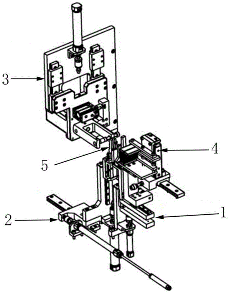

Image

  • Wire twisting mechanism for T1 ring wire winding machine
  • Wire twisting mechanism for T1 ring wire winding machine
  • Wire twisting mechanism for T1 ring wire winding machine

Examples


Embodiment Construction

[0020] In order to make the object, technical solution and advantages of the present invention clearer, the present invention will be further described in detail below in conjunction with the accompanying drawings and embodiments. It should be understood that the specific embodiments described here are only used to explain the present invention, not to limit the present invention.

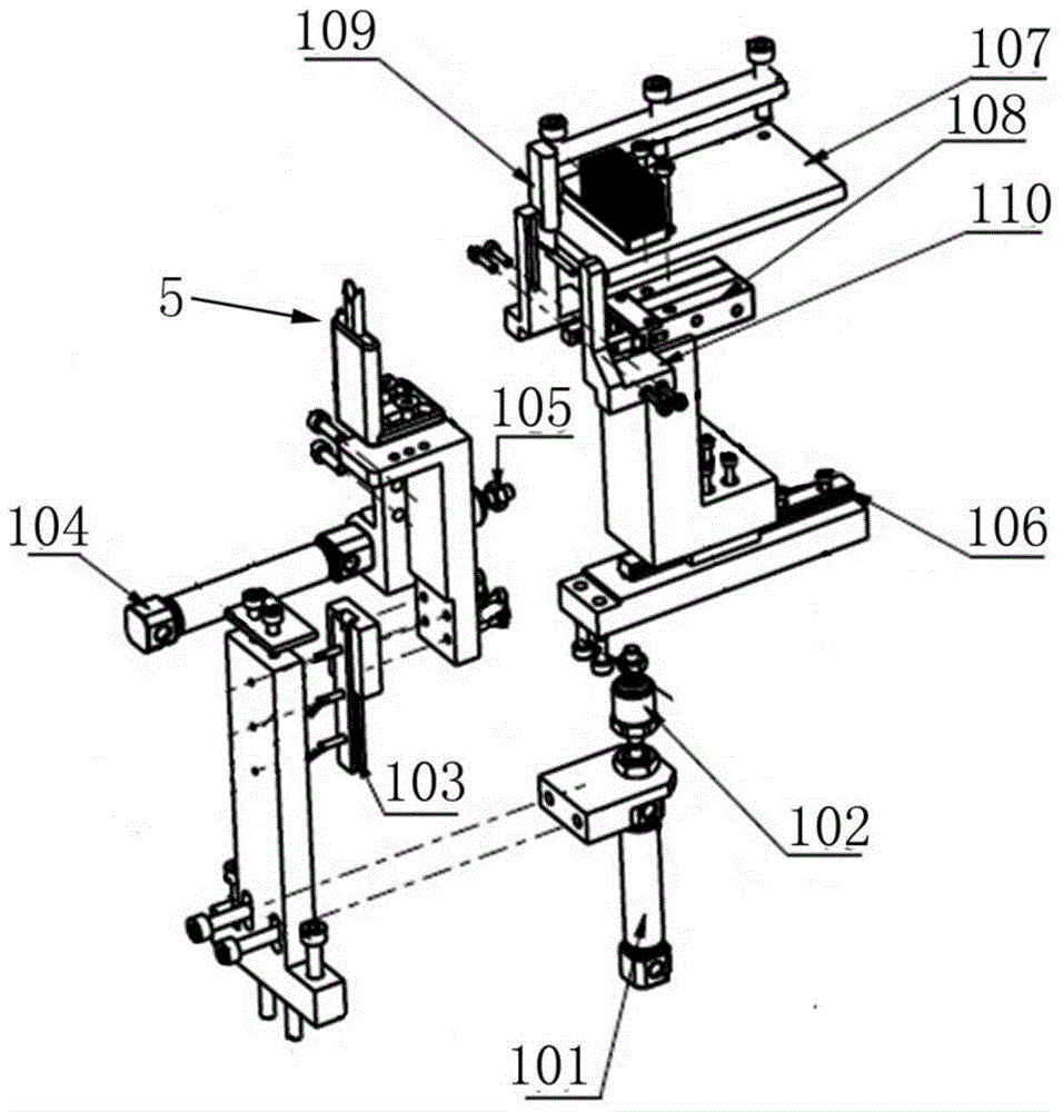
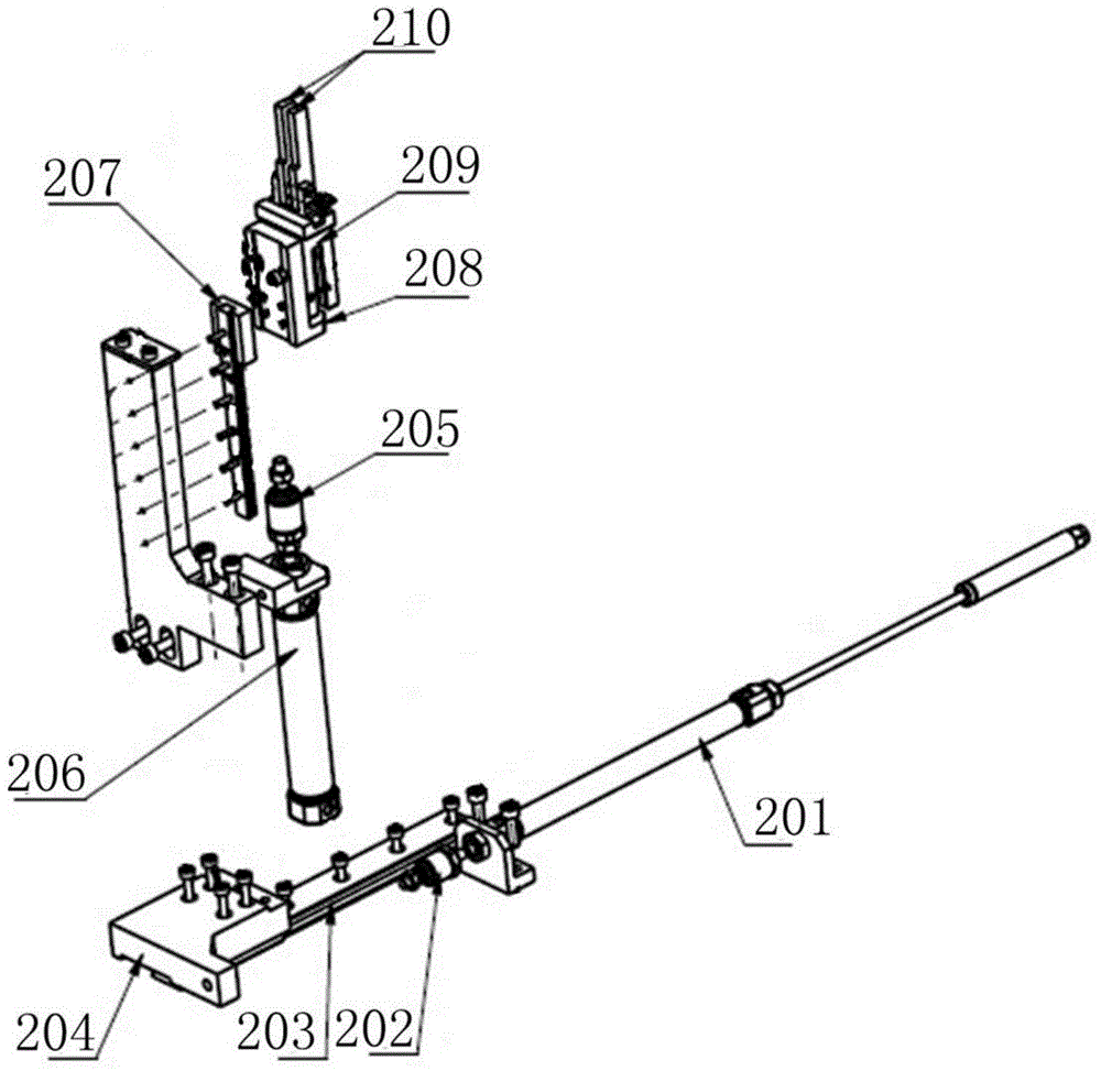
[0021] See figure 1 , figure 2 , a twisting mechanism of a T1 winding wire machine in the present invention, including a wire tail clamping assembly 1 for clamping the wire tail of the T1 ring after winding, and a wire end for clamping the two wire ends used to wind the T2 ring The clamping assembly 2, the T1 ring clamping assembly 5 for clamping the T1 ring, the twisted wire assembly 3 for the twisted wire of the wire end and the carding assembly 4 for making the T1 ring wire head and wire tail straight after winding, wherein The thread tail clamping assembly 1 is connected to the thread end cl...


PUM


Abstract

The invention provides a wire twisting mechanism for a T1 ring wire winding machine. The wire twisting mechanism comprises a wire head clamping assembly, a wire tail clamping assembly, a T1 ring fixing assembly and a wire twisting assembly. The T1 ring fixing assembly is located between the wire head clamping assembly and the wire tail clamping assembly and the wire twisting assembly is arranged above the wire head clamping assembly. By the adoption of the wire twisting mechanism for the T1 ring wire winding machine, two varnished wires needing to be wound around a T2 ring can be automatically twisted before the vanished wires are wound around the T2 ring, and great convenience is provided for automatic conduction of following processes such as the T2 ring winding process.

Description

technical field [0001] The invention relates to a network transformer winding machine, in particular to a twisting mechanism of a T1 winding machine of a fully automatic network transformer winding machine. technical background [0002] Networks are ubiquitous in today's world. Network transformers are the main electronic components of network equipment. In the past, network transformers were still in a state of full manual production. The manual production process includes: manual winding of T1 rings; manual taps and stranded wires of T1 rings; Fixture, and manually wind the T2 ring. [0003] With the advancement of technology, the winding of the T1 ring can be automatically realized by the machine, but before the winding of the T2 ring, it is necessary to tap the wire after the T1 ring and then twist the wire, and then perform the T2 winding wire. It is relatively complicated, so the manufacture of network transformers now often needs to complete the winding of the T1 rin...

Claims


Application Information

Patent Timeline
Patent Type & Authority Applications(China)
IPC IPC(8): H01F41/08
Inventor 陈新裕吉东亚吴金辉
Owner ZHUHAI HENGNUO SCI & TECH CO LTD
Learn More