
Electric tool

A technology of electric tools and power supplies, which is applied in the direction of electrical components, emergency protection circuit devices, etc., and can solve the problems of bolts that are easy to fall, fall, and easy to lose, and achieve the effect of avoiding falling and preventing loosening and falling off

Active Publication Date: 2015-07-22
JIANGSU DONGCHENG TOOLS TECH CO LTD
View PDF3 Cites 5 Cited by
  • Summary
  • Abstract
  • Description
  • Claims
  • Application Information

AI Technical Summary

Problems solved by technology

The result of this is that, since the rotation speed of the tool is usually relatively fast, if the trigger is not turned off in time during the process of removing the fastener, the fastener is very easy to be rotated loose and fall
Especially in the case of high-altitude operations, such as when the operator performs bolt removal operations on the scaffolding, the bolts are very easy to fall, and the dropped bolts are easy to hurt people when they fall from a high altitude, and they are also easy to lose. New bolts need to be replaced etc., which brings a lot of inconvenience to the operator

Method used


Image

  • Electric tool
  • Electric tool
  • Electric tool

Examples


Embodiment 1

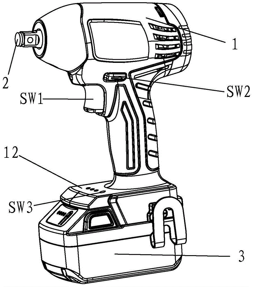
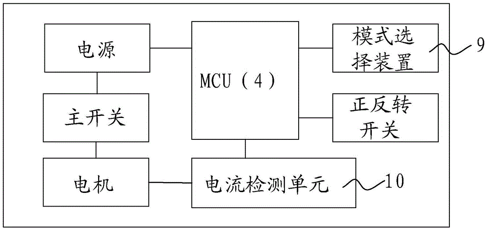
[0026] Reference attached figure 1 and attached image 3 As shown in the electric tool, the electric tool mainly includes a housing 1, a motor (not shown in the figure) located in the housing, a working head 2 driven by the motor, a battery pack 3 connected to the tool body as a power source, and a control motor The start / stop main switch SW1 and a controller MCU4, the controller MCU4 can receive the signals of the main switch SW1, the forward and reverse switch SW2, the mode selection switch SW3 and the current detection unit 10, and accordingly control the motor to perform corresponding actions.

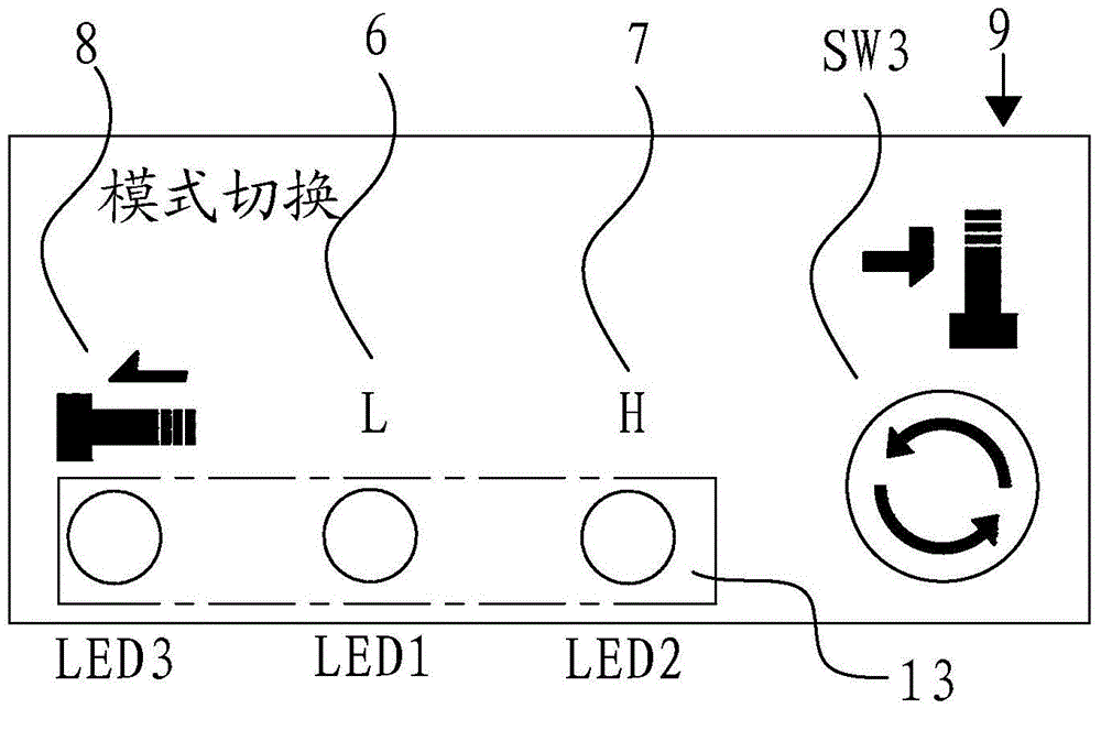
[0027] Reference attached image 3 And attached Figure 4 As shown, the power tool has three working gears, low torque gear 6, high torque gear 7 and fastener withdrawal gear 8. The operator can switch among the three working gears by pressing the mode selection switch SW3 of the mode selecting device 9, and the operator can know the selected working gear through the LED light o...

Embodiment 2

[0032] Refer to attached Figure 7 And attached Figure 8 As shown, compared with Embodiment 1, in Embodiment 2, the electric tool does not have a mode selection device and a display device, and the others are basically the same as Embodiment 1. The operator triggers the main switch SW1 to turn on the motor power, the controller MCU14 receives the signals of the main switch SW1 and the forward and reverse switch SW2, if the forward and reverse switch SW2 is in the forward position, the controller MCU14 adjusts the duty of the output current To adjust the output torque and speed of the brushless motor, if the forward and reverse switch SW2 is in the reverse position, the controller MCU14 receives the sampled current value from the current detection unit 20, and compares the current value with the pre-stored value in the controller MCU14 Compared with the preset current value, if the motor current value is continuously lower than the preset current value within a predetermined ...


PUM


Abstract

The invention relates to an electric tool which has an automatic reverse rotation stop function. Under a fastener retreating gear (8) of the electric tool, a control device (4) receives setting from a forward and reverse rotation switch (SW2) and a current value collected by a current detection device (10) after an operator triggers a main switch (SW1); when a motor rotates reversely, the current value is compared with a preset current value prestored in the control device (4), and if the current value is continuously smaller than the preset current value within a preset time, motor supply motor is turned off. During reverse rotation of a retreating fastener and when the fastener is not completely released from the surface of a workpiece, the tool stops running automatically, and falling off of the fastener is effectively prevented.

Description

【Technical field】 [0001] The invention relates to an electric tool, in particular to an electric tool with the function of removing fasteners. 【Background technique】 [0002] At present, the electric tools on the market, such as screwdrivers, impact wrenches, etc., when reversing the fastener, unless the operator releases the trigger and cuts off the motor current, the electric tool will stop rotating, otherwise the electric tool will stop. turn. The result of this is that since the rotating speed of the tool is usually relatively fast, if the trigger is not turned off in time during the process of withdrawing the fastener, the fastener is very easy to be rotated and loosened and dropped. Especially in the case of high-altitude operations, such as when the operator performs bolt removal operations on the scaffolding, the bolts are very easy to fall, and the dropped bolts are easy to hurt people when they fall from a high altitude, and they are also easy to lose. New bolts n...

Claims


Application Information

Patent Timeline
Patent Type & Authority Applications(China)
IPC IPC(8): H02H7/08
Inventor 侯维平
Owner JIANGSU DONGCHENG TOOLS TECH CO LTD
Learn More