
Multiphase DC-DC converter

A technology of DC-DC and converter, applied in the field of DC-DC converter, can solve the problem of high ripple current of output capacitor

Inactive Publication Date: 2015-07-22
ASTEC INT LTD
View PDF10 Cites 8 Cited by
  • Summary
  • Abstract
  • Description
  • Claims
  • Application Information

AI Technical Summary

Problems solved by technology

Otherwise, the ripple current in the output capacitor will be higher

Method used


Image

  • Multiphase DC-DC converter
  • Multiphase DC-DC converter
  • Multiphase DC-DC converter

Examples


Embodiment Construction

[0025] Embodiments of the present invention will be described below with reference to the drawings. Elements and features described in one drawing or one embodiment of the present invention may be combined with elements and features shown in one or more other drawings or embodiments. It should be noted that representation and description of components and processes that are not related to the present invention and known to those of ordinary skill in the art are omitted from the drawings and descriptions for the purpose of clarity.

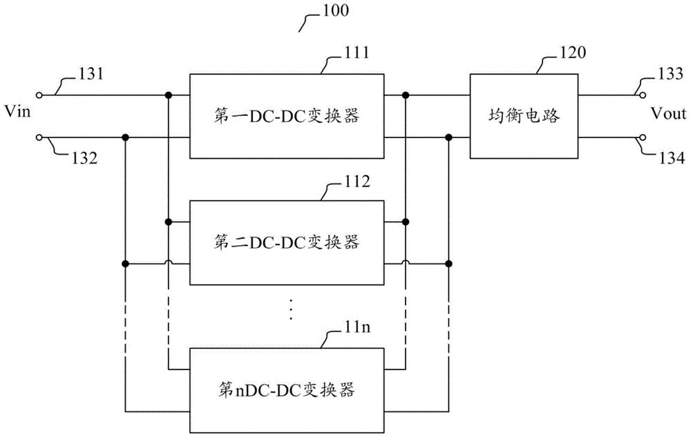
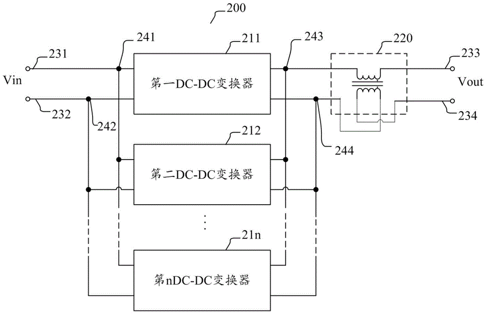
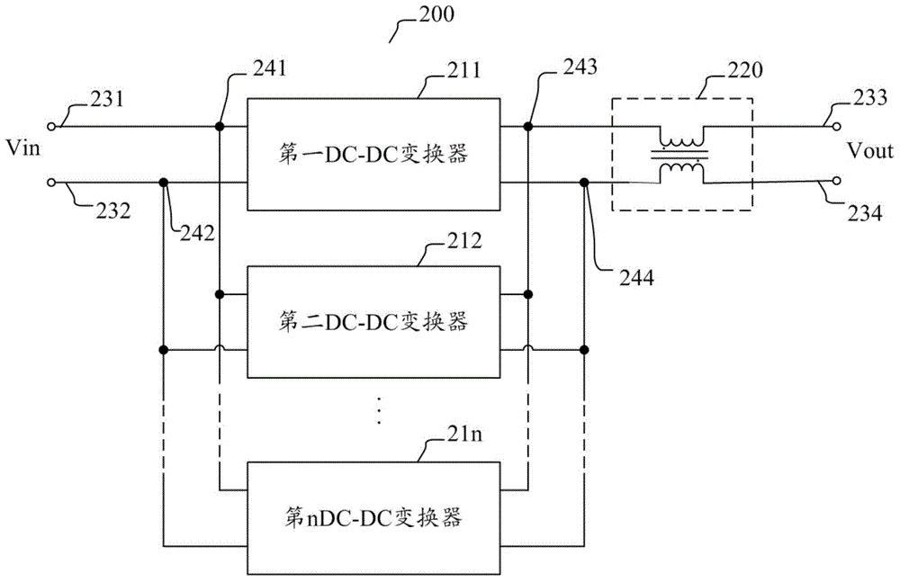
[0026] In an embodiment of the present invention, multiple single-phase DC-DC converters are balanced by using an equalization circuit connected in series between the input and output terminals of the multi-phase DC-DC converter with multiple single-phase DC-DC converters connected in parallel. - DC converter current, reducing the difference between the currents of multiple single-phase DC-DC converters, thereby achieving acceptable current sharing...


PUM


Abstract

The invention discloses a multiphase DC-DC converter including an input end for receiving DC input voltage, a plurality of parallelly connected single-phase DC-DC converters for performing DC-DC conversion on DC input voltage, an output end for outputting the DC output voltage converted by the plurality of single-phase DC-DC converters, and an equalization circuit which is serially connected with the plurality of parallelly connected single-phase DC-DC converters between the input end and the output end of the multiphase DC-DC converter and is used for equalizing the current of the single-phase DC-DC converters.

Description

technical field [0001] The present invention relates generally to the field of converters, and more particularly to a DC-DC converter with a multi-phase architecture. Background technique [0002] The statements in this section merely provide background information related to the present disclosure and may not constitute prior art. [0003] Various types of direct current-direct current (DC-DC) converters are known. For example, multiphase DC-DC converters are known which employ two or more independent single-phase DC-DC converters connected in parallel. For example, in a multiphase DC-DC converter employing two single-phase DC-DC converters, the output currents of the two single-phase DC-DC converters are shifted in phase by 90°. This results in a current overlapping current at the output of the multiphase DC-DC converter, thereby reducing the ripple current in the output capacitor. Additionally, the resonant components must be well matched to achieve acceptable current ...

Claims


Application Information

Patent Timeline
IPC IPC(8): H02M3/00H02M3/335H02M1/14
CPCH02M3/00H02M3/3353H02M1/007
Inventor 刘军徐光伟张迁汪伟峰
Owner ASTEC INT LTD
Learn More