
Intergrated circuit

A technology of integrated circuits and power sources, which is applied in the field of integrated circuits in the core power domain, and can solve the problem that the power consumption of integrated circuits cannot be reduced.

Active Publication Date: 2015-07-22
MEDIATEK INC
View PDF3 Cites 0 Cited by
  • Summary
  • Abstract
  • Description
  • Claims
  • Application Information

AI Technical Summary

Problems solved by technology

[0003] In order to solve the technical problem that the power consumption in the above-mentioned integrated circuit cannot be reduced, the present invention provides a new type of integrated circuit

Method used


Image

  • Intergrated circuit
  • Intergrated circuit
  • Intergrated circuit

Examples


Embodiment Construction

[0012] Certain terms are used in the description and claims to refer to particular components. Those skilled in the art should understand that hardware manufacturers may use different terms to refer to the same component. The specification and claims do not use the difference in name as a way to distinguish components, but use the difference in function of components as a criterion for distinguishing. The "comprising" mentioned throughout the specification and claims is an open term, so it should be interpreted as "including but not limited to". In addition, the term "coupled" herein includes any direct and indirect means of electrical connection. Therefore, if it is described that the first device is coupled to the second device, it means that the first device may be directly electrically connected to the second device, or indirectly electrically connected to the second device through other devices or connection means.

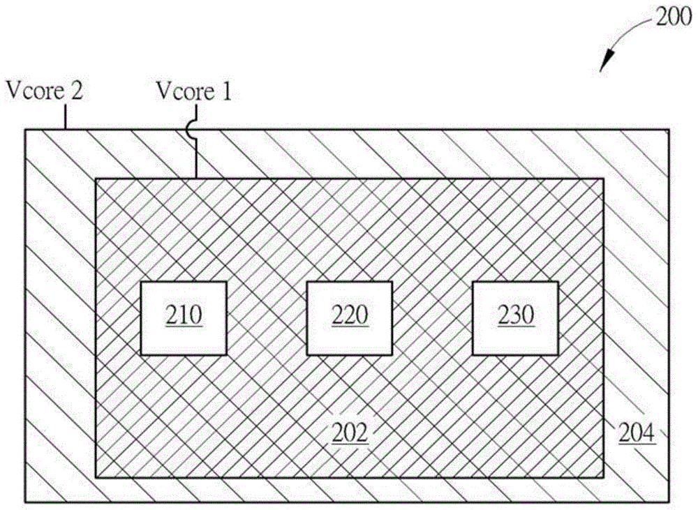
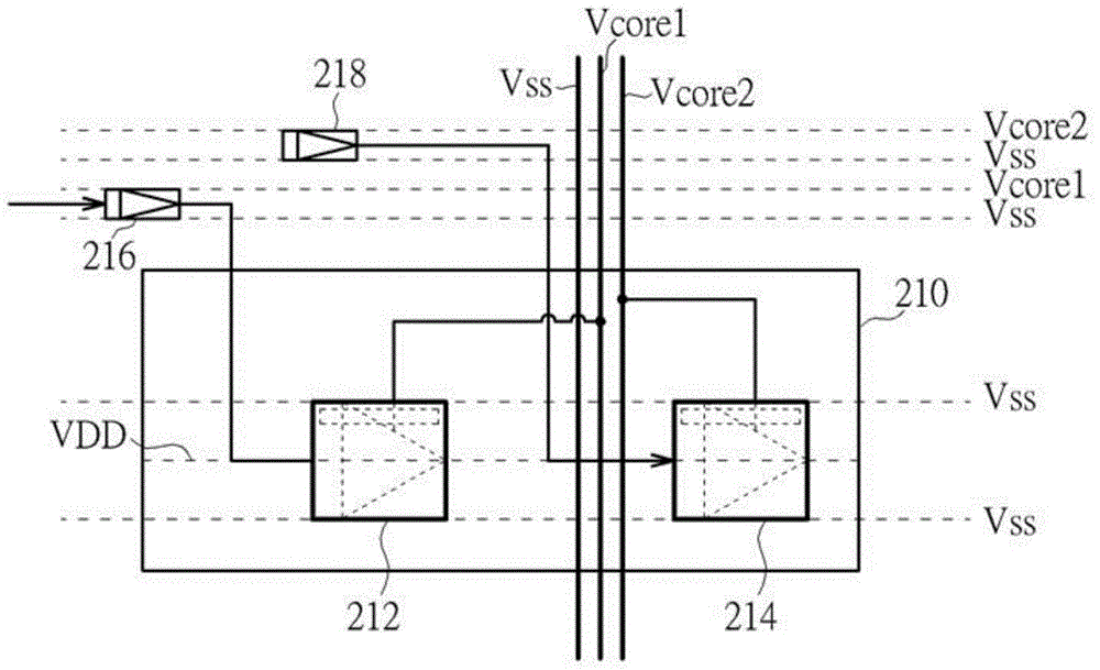
[0013] Please refer to figure 2 , figure 2 Shown ...


PUM


Abstract

The present invention provides an intergrated circuit. The intergrated circuit comprises: a plurality of core power sources; and a plurality of core power domains, coupled to the core power sources, respectively; wherein the core power domains are overlapped with each other.

Description

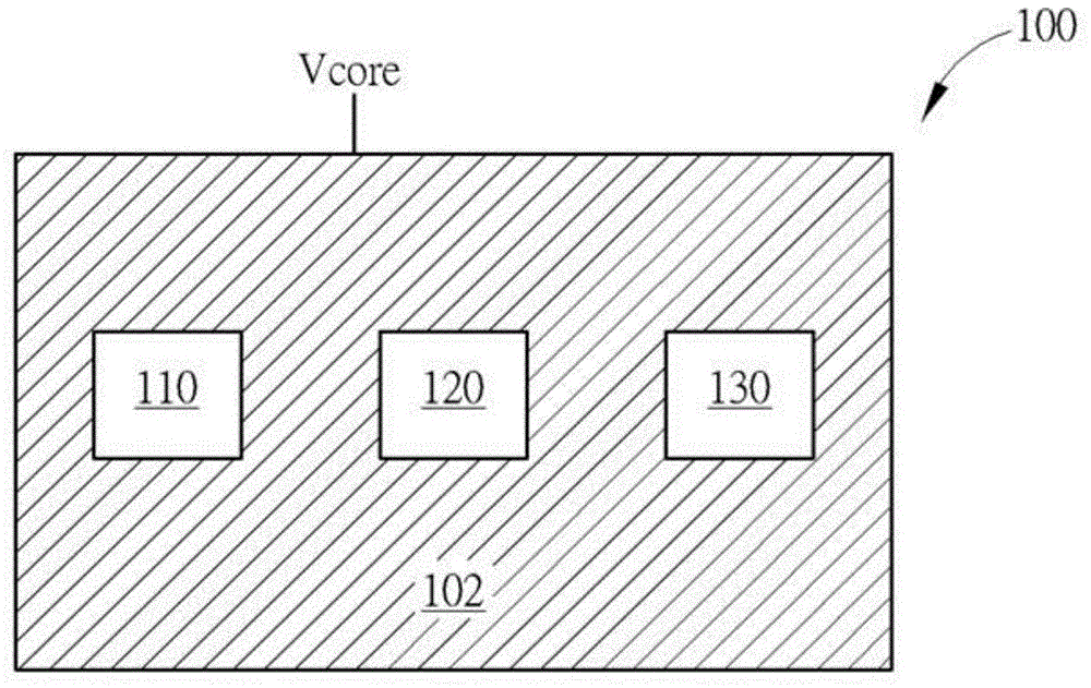
technical field [0001] The present invention relates to an integrated circuit, in particular to an integrated circuit including a plurality of overlapping core power domains. Background technique [0002] Please refer to figure 1 , figure 1 Shown is a simplified block schematic diagram of a conventional integrated circuit 100 . Such as figure 1 As shown, the integrated circuit 100 includes: a core power source (core power source) Vcore, a core power domain (core power domain) 102 and three power domains 110, 120, 130, wherein the power domains 110, 120, 130 are all coupled to In the core power source Vcore. Since there is only one core power source and the core power source must be continuously on, no components in the power domains 110 , 120 , 130 can be turned off or stepped down, so the IC 100 has the disadvantage that the power consumption cannot be effectively reduced. Contents of the invention [0003] In order to solve the technical problem that the power consu...

Claims


Application Information

Patent Timeline
IPC IPC(8): H03K19/0175
CPCH02J4/00H02J9/005G06F1/3287Y02D10/00G06F1/3234H01L23/5286
Inventor 林志青高亦平苏峻松
Owner MEDIATEK INC
Learn More