Ultrasonic energy control circuit for interventional therapy

A technology of interventional therapy and energy control, which is applied in the field of ultrasound, can solve problems such as inability to apply ultrasound energy stability requirements and unstable ultrasound energy, and achieve the effect of improving stability and ensuring stability

Active Publication Date: 2018-07-06
LEPU MEDICAL TECH (BEIJING) CO LTD
View PDF4 Cites 0 Cited by
  • Summary
  • Abstract
  • Description
  • Claims
  • Application Information

AI Technical Summary

Problems solved by technology

[0004] Because the ultrasonic generating devices in the prior art are all used to detect lesions, that is, determine the lesion position in the human body by emitting ultrasonic waves, and the ultrasonic emitting devices in the prior art cannot be applied to ultrasonic energy due to the unstable ultrasonic energy emitted. Treatment of intravascular diseases with very high stability requirements

Method used


Image

  • Ultrasonic energy control circuit for interventional therapy
  • Ultrasonic energy control circuit for interventional therapy
  • Ultrasonic energy control circuit for interventional therapy

Examples


Embodiment 1

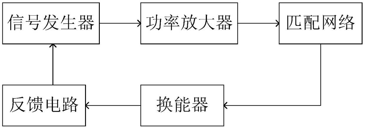
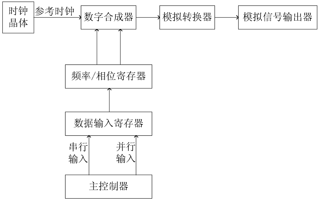
[0032] refer to figure 2 , in this embodiment, the signal generator includes: a clock crystal, a main controller, a digital synthesizer and an analog converter, the clock crystal is used to generate a reference clock, and output to the digital synthesizer, the main The controller transmits the frequency and phase to the digital synthesizer, the digital synthesizer sends the synthesized signal to the analog converter, and the analog converter performs digital-to-analog conversion to obtain the frequency and phase Corresponding to the sine wave, the master controller receives the detected power, frequency and impedance.

[0033] In this embodiment, a data input register and a frequency / phase register are further included between the main controller and the digital synthesizer, and the main controller transmits the frequency and phase to the stored in the data input register, then forwarded to the frequency / phase register, and finally the frequency and phase are transmitted to ...

Embodiment 2

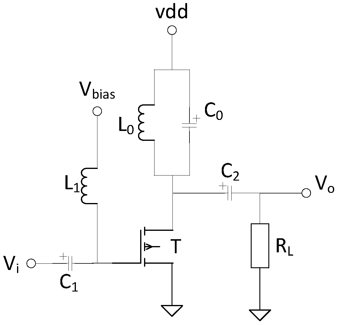
[0036] refer to image 3 , in this embodiment, the power amplifier includes: a field effect transistor T and a resistor R L , the gate of the field effect transistor T and the output terminal V of the signal generator i and bias voltage V bias respectively connected, the source of the field effect transistor T is connected to the high level vdd, the output terminal V of the power amplifier o and the resistor R L The first ends are respectively connected, the resistor R L The second end of the ground, the bias voltage V bias and the gate of the field effect transistor T is provided with an inductor L 1 , the resistor R L A first capacitor C is connected between the first end of the field effect transistor T and the source 2 , an LC parallel circuit is connected between the high level vdd and the source of the field effect transistor T (that is, L in the figure 0 and C 0 ), the gate of the field effect transistor T and the output terminal V of the signal generator i A ...

Embodiment 3

[0040] refer to Figure 4 , in this embodiment, the power amplifier includes: a power coupler, a power divider, a resistor R L and two FETs T 1 , T 2 , the input of the power divider and the output of the signal generator V i connected, the two outputs of the power divider are connected to the two FETs T 1 , T 2 The gates are connected in one-to-one correspondence, the two field effect transistors T 1 , T 2 The drains of both FETs are grounded, the two FETs T 1 , T 2 The source poles of the power coupler are respectively connected to the two input terminals of the power coupler in one-to-one correspondence, and the output terminal of the power coupler is connected to the output terminal V of the power amplifier. o and the resistor R L The first ends are respectively connected, the resistor R L The second terminal of the ground, the output terminal of the power coupler and the resistor R L A capacitor C is provided between the first terminals of the 1 , the resistor...


PUM


Abstract

The invention discloses an ultrasonic energy control circuit for interventional therapy, which relates to the field of ultrasonic technology. The control circuit includes: a signal generator, a power amplifier, a matching network, an ultrasonic transducer and a feedback circuit connected in sequence, and the feedback circuit Connected with the signal generator, the signal generator is used to generate a sine wave, the power amplifier is used to amplify the signal of the sine wave, and the matching network is used to perform impedance and power analysis on the amplified sine wave. Matching, the ultrasonic transducer is used to transform the sine wave with impedance and power matching into electrical energy / mechanical energy, the feedback circuit is used to detect the power, frequency and impedance of the ultrasonic transducer, and convert the detected Power, frequency and impedance are sent to the signal generator. The invention realizes the automatic tracking and stabilization by setting the feedback circuit, so as to ensure the stability of the ultrasonic energy of the ultrasonic emitting device.

Description

technical field [0001] The invention relates to the field of ultrasonic technology, in particular to an ultrasonic energy control circuit for interventional therapy. Background technique [0002] Ultrasonic waves refer to mechanical waves with a sound source vibration frequency greater than 20,000Hz propagating in elastic media, and have the following physical characteristics: (1) Good directionality. Due to the high frequency and short wavelength of ultrasound, which is close to the wavelength of infrared rays, it has strong directionality like light, forms an ultrasound beam, can propagate in a certain direction, and can emit ultrasound energy directionally; (2) Reflection and transmission. When ultrasonic waves encounter interfaces formed by different tissue densities during propagation in the body, part of them will generate reflected waves, and the other part can pass through the interface and enter deep tissues. When the transmitted wave encounters the deep interface,...

Claims


Application Information

Patent Timeline
Patent Type & Authority Patents(China)
IPC IPC(8): H03L7/08
Inventor 王挺许天刚董飒英蒲忠杰赵士勇杨永森王超黄晶
Owner LEPU MEDICAL TECH (BEIJING) CO LTD
Why Eureka
Try Eureka