Check patentability & draft patents in minutes with Patsnap Eureka AI!

EMC circuit

A circuit and filter circuit technology, which is applied in the field of electronic ballasts, can solve the problems of not being able to meet the requirements of the high frequency band, not being able to meet the middle frequency band, and the filtering effect of the primary common mode filter circuit is not good enough, etc.

Inactive Publication Date: 2015-07-22
谢晶
View PDF0 Cites 4 Cited by
  • Summary
  • Abstract
  • Description
  • Claims
  • Application Information

AI Technical Summary

Problems solved by technology

[0003] In order to illustrate the effect of the differential mode filter circuit and common mode filter circuit in the filter circuit on suppressing conducted interference, the frequency range 9kHZ to 30MKZ for electronic ballast EMC testing is generally divided into three frequency bands: low, medium and high, namely 9-150kHZ Left and right, 150kHZ-2.0MKZ around, 2.0-30MKZ three bands, for the 9kHz-150kHz low frequency band, it is more effective to use a differential mode filter circuit; for the 150kHz-30MKZ medium and high frequency bands, it is more effective to use a common mode filter circuit, sometimes using a The filtering effect of the first-stage common-mode filter circuit is not good enough, and a two-stage common-mode filter circuit is also used, such as figure 2 As shown, it is difficult for the above traditional filter circuit to meet the requirements for EMC testing in the mid-frequency band and high-frequency band at the same time
In the selection of parameters, it often meets the requirements of the mid-frequency band, but cannot meet the requirements of the high-frequency band, or conversely, meets the requirements of the high-frequency band, but cannot meet the requirements of the mid-frequency band, and it is difficult to take into account the requirements of both aspects.

Method used


Image

  • EMC circuit
  • EMC circuit
  • EMC circuit

Examples


Embodiment l

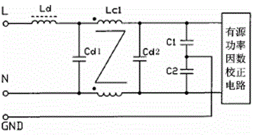
[0014] Embodiment 1, appended image 3 It is a circuit diagram of an EMC circuit, including a differential mode filter circuit and a common mode filter circuit connected in sequence, the common mode filter circuit is electrically connected to an active power factor correction circuit, and the differential mode filter circuit includes a differential mode inductance Ld, a differential mode capacitor Cdl and a differential mode Mode capacitor Cd2, common mode filter circuit includes common mode inductor LCl, common mode capacitor Cl and common mode capacitor C2, differential mode inductor Ld and differential mode capacitor Cdl are connected in series at both ends of the power supply, common mode inductor LCl and differential mode capacitor Cd2 and The differential mode capacitor Cd1 is connected in parallel, the common mode capacitor Cl and the common mode capacitor C2 are connected in parallel with the differential mode capacitor Cd2 after being connected in series, and the joint...

Embodiment 2

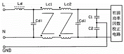
[0028] Embodiment 2, with Figure 4 It is a circuit diagram of an EMC circuit, including a differential mode filter circuit and a common mode filter circuit connected in sequence, the common mode filter circuit is electrically connected to an active power factor correction circuit, and the differential mode filter circuit includes a differential mode inductance Ld, a differential mode capacitor Cdl and a differential mode Mode capacitor Cd2, the common mode filter circuit includes common mode inductor LCl, common mode inductor LC2, common mode capacitor Cl and common mode capacitor C2, differential mode inductor Ld and differential mode capacitor Cdl are connected in series at both ends of the power supply, differential mode capacitor Cd2 and The differential mode capacitor Cdl is connected in parallel, the common mode inductor LCl and the common mode inductor LC2 are connected in parallel with the differential mode capacitor Cdl, the common mode capacitor Cl and the common mod...


PUM


Abstract

The invention relates to an EMC circuit which comprises a differential mold filtering circuit and a common mold filtering circuit which are connected in sequence. The common mold filtering circuit comprises a common mold capacitance C1 and a common mold capacitance C2 which are connected in series, wherein the contacts of the common mold capacitance C1 and the common mold capacitance C2 are connected with a grounding wire, and an inductance L is arranged on the grounding wire. The EMC circuit can effectively restrain the influence of the triangular wave in the input current on the conducted interference, not only can meet the requirements for the input current harmonic content limit value of the electronic ballast which is larger than 25W by the national standard GBl7625 1998, but also can meet the requirements for the EMC by the national standard GBl7743 1999, and can meet the requirements for the EMC by the national standard GBl7743 1999 in the middle-frequency band and the high-frequency band.

Description

technical field [0001] The invention relates to an electronic ballast, in particular to an EMC circuit used in an active power factor correction circuit in the electronic ballast, and belongs to the technical field of the electronic ballast. Background technique [0002] The input current in the active power factor circuit is a series of triangular waves with varying frequency, and its spectrum is very rich. To suppress the influence of the triangular wave in the input current on the conduction interference, a complex passive filter circuit must be used. The traditional passive filter circuit is attached as figure 1 As shown, the passive filter circuit includes a differential-mode filter circuit and a common-mode filter circuit, the differential-mode filter circuit includes a differential-mode inductor Ld, a differential-mode capacitor Cd1 and a differential-mode capacitor Cd2, and the common-mode filter circuit includes a common-mode inductor LCl, a common-mode Capacitor C...

Claims


Application Information

Patent Timeline
IPC IPC(8): H05B41/14H02M1/44H02J3/18
CPCY02E40/30
Inventor 谢晶
Owner 谢晶
Features
  • R&D
  • Intellectual Property
  • Life Sciences
  • Materials
  • Tech Scout
  • Unparalleled Data Quality
  • Higher Quality Content
  • 60% Fewer Hallucinations
Learn More