Optical sensor unit

A technology of optical sensors and unit shells, which is applied in the direction of instruments, electrical components, scientific instruments, etc., can solve the problems of light leakage detection accuracy, manufacturing energy consumption, and reduction, so as to achieve yield rate, increase manufacturing efficiency, and prevent printed wiring The effect of disconnection

Inactive Publication Date: 2015-07-22
ALPHA
View PDF4 Cites 8 Cited by
  • Summary
  • Abstract
  • Description
  • Claims
  • Application Information

AI Technical Summary

Problems solved by technology

[0008] However, in the above-mentioned conventional example, since the partition wall is formed by a mold or the like, there is a problem that manufacturing is laborious.
In addition, in order to solve this problem, it is also possible to assemble a separate partition wall member, but in this case, there is a problem that light leakage is likely to occur from the boundary with the partition wall member and the detection accuracy is reduced.

Method used


Image

  • Optical sensor unit
  • Optical sensor unit
  • Optical sensor unit

Examples


Embodiment Construction

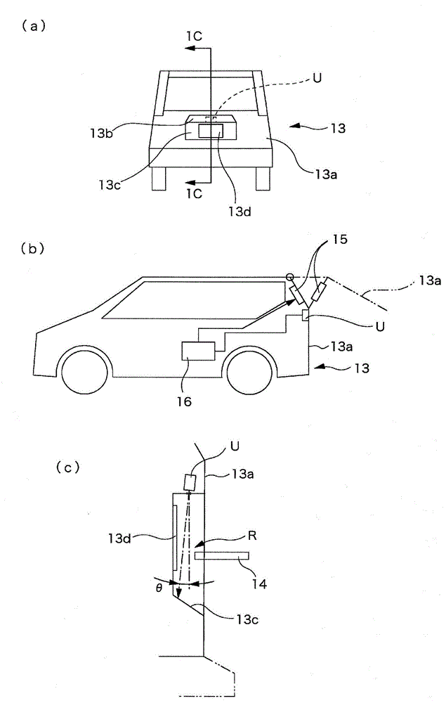
[0031] figure 1 A vehicle 13 to which the present invention is applied is shown. In this example, the photosensor unit (U) is used while being fixed to the rear door 13a in order to control the opening and closing operation of the rear door 13a of the vehicle.

[0032] As will be described later, the optical sensor unit (U) is configured to output a detection signal when detecting that the detection object 14 enters a predetermined detection area (R) onto which detection light is projected, and the optical sensor unit (U) is fixed to the The top wall portion of the license plate mounting recess 13c surrounded by the license plate decoration 13b. It should be noted that, in figure 1 In , reference numeral 13d denotes a car license plate.

[0033] Also, in this example, the optical axis of the detection light is slightly inclined toward the vehicle inner side (angle θ) so that the center of the detection area (R) of the photosensor unit (U) is located in the license plate mou...


PUM


Abstract

An object of the present invention is to provide a photosensor unit with a structure which is simple and does not lower the detection accuracy. Provided is a photosensor unit configured such that reflected light of detection light emitted from one or more light emitting elements 2 housed in a unit case 1 to the outside of the unit case 1 is detected with a light receiving element 4 mounted on a mounting board 3, the reflected light being reflected from a detection region set on the outside of the unit case 1. A passage space for the reflected light inside the unit case 1 is separated from the other space in the unit case 1 by a partition member 6 placed on the mounting board 3 with an annular packing 5 therebetween which surrounds the light receiving element 4 and is made of an elastic material. The partition member 6 is provided with a pressing wall 7 configured to come into pressure contact with the outer peripheral wall of the annular packing 5 when the partition member 6 is placed on the mounting board 3, and thereby apply pressure contact force to the annular packing 5 while dividing the pressure contact force in a radially compressing direction, the pressure contact force being force with which the annular packing 5 comes into contact with the mounting board 3.

Description

technical field [0001] The present invention relates to light sensor units. Background technique [0002] An optical sensor unit described in Patent Document 1 is known as an optical sensor unit in which a light emitting element and a light receiving element are accommodated in a unit case. [0003] In this conventional example, in order to prevent interference between the light-emitting element and the light-receiving element, each light passing region is partitioned by a partition wall made of a resin formed body. [0004] prior art literature [0005] patent documents [0006] Patent Document 1: Japanese Patent Laid-Open No. 2012-18110 [0007] The problem to be solved by the invention [0008] However, in the conventional example described above, since the partition wall is formed by a mold or the like, there is a problem that manufacturing requires labor. In addition, in order to solve this problem, a partition wall member formed separately may be incorporated, but...

Claims


Application Information

Patent Timeline
IPC IPC(8): H01L31/12B60J5/00B60J5/10G01S17/04
CPCB60J5/00G01J1/06H01L31/12G01S17/026G01J1/0271G01S7/4813B60J5/10H01L31/16G01S17/04
Inventor 冈田高裕
Owner ALPHA
Why Eureka
Try Eureka