Care device for head skin

A conditioner and scalp technology, used in kneading massage appliances, physiotherapy, vibration massage, etc., can solve the problem that it is difficult to effectively massage the convex curved scalp, etc., and achieve the effect of easily and stably maintaining the frame

Active Publication Date: 2015-07-29
TWINBIRD CORP
View PDF8 Cites 12 Cited by
  • Summary
  • Abstract
  • Description
  • Claims
  • Application Information

AI Technical Summary

Problems solved by technology

[0005] Such a scalp conditioner requires a combination of spur gears to transmit the rotation of the motor, so the rotating surfaces of

Method used


Image

  • Care device for head skin
  • Care device for head skin
  • Care device for head skin

Examples


Embodiment 1

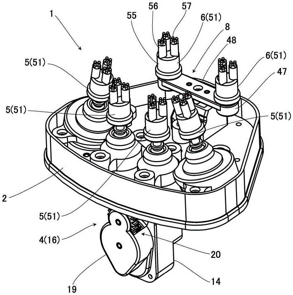
[0036] Figure 1 to Figure 11 Example 1 is shown. 1 is the scalp conditioner of the present invention. This scalp conditioner 1 includes a frame 2 , a motor 3 , a transmission mechanism 4 for transmitting the rotational motion of the motor 3 , and a rotating treatment element 5 and a reciprocating treatment element 6 as treatment elements connected to the transmission mechanism 4 . Furthermore, the above-mentioned motor 3 and transmission mechanism 4 are supported on the above-mentioned frame 2 . In addition, the above-mentioned transmission mechanism 4 is provided with a rotation mechanism part 7 and a conversion mechanism part 8 for converting the rotation of the rotation mechanism part 7 into a reciprocating motion. A plurality of above-mentioned reciprocating treatment members 6 are connected to the mechanism part 8 .

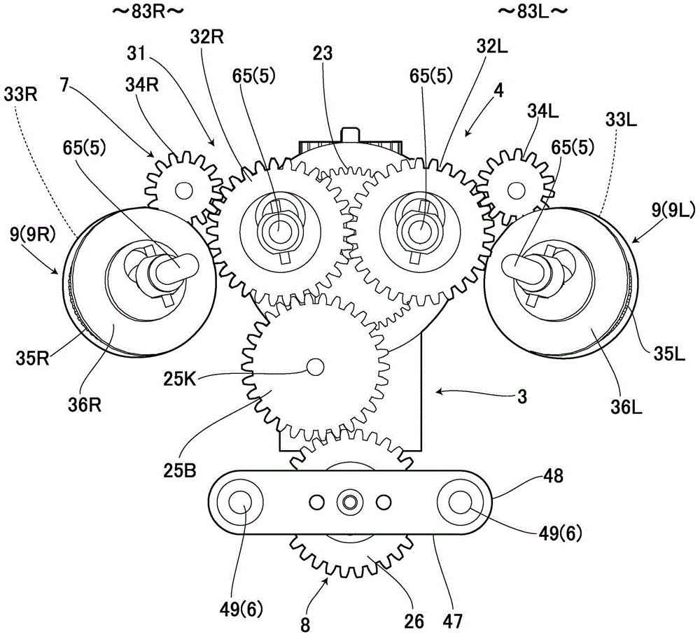
[0037] Such as image 3 As shown in FIG. 2, the above-mentioned motor 3 has a drive shaft 3A on the front side through a gear housing 14, and a drive ge...

Embodiment 2

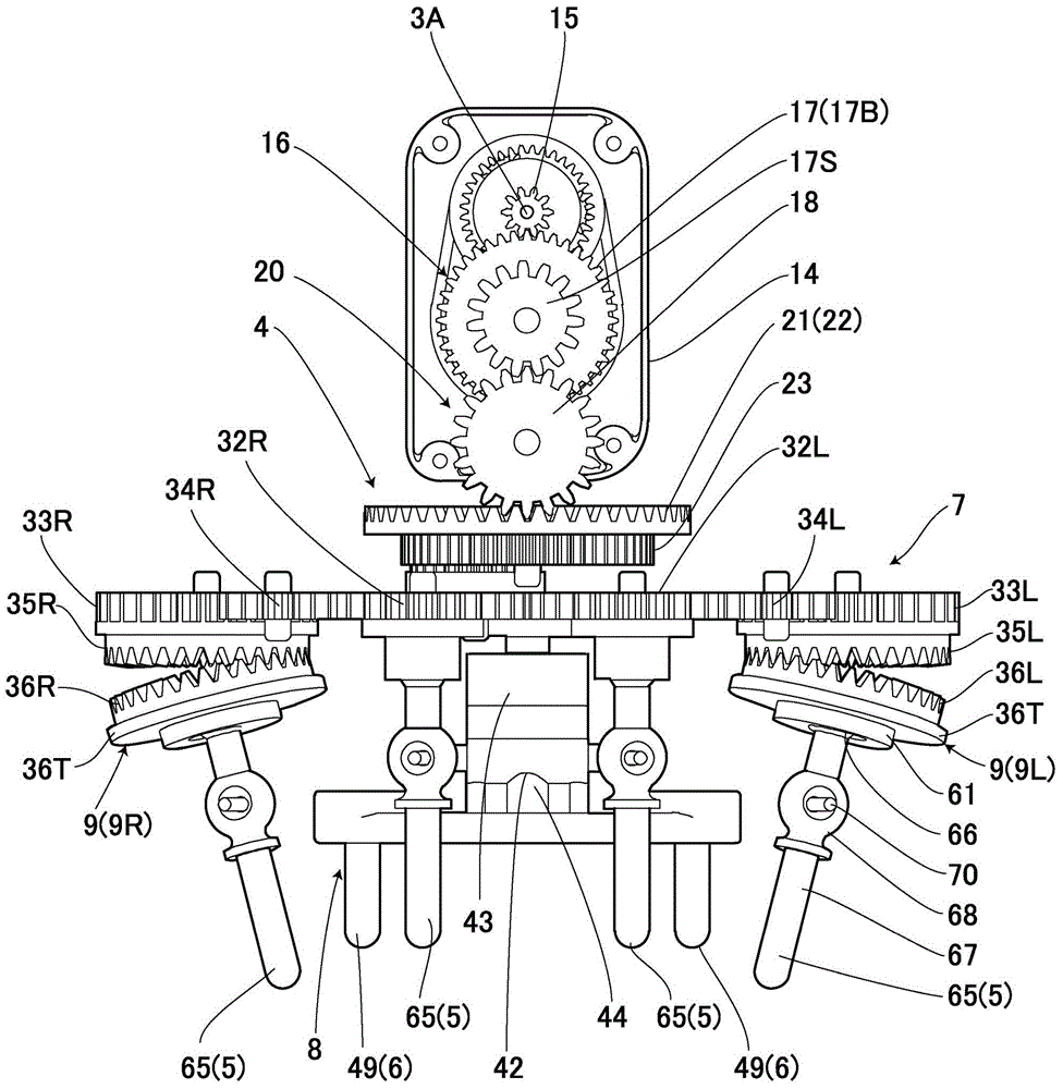
[0068] Figure 13 to Figure 19 Example 2 of the present invention is shown, and the same parts as in the above-mentioned Example 1 are assigned the same symbols, and the description thereof will be omitted for detailed description. In this example, the motor 3 is arranged vertically, the gear housing 14 is arranged at the lower part thereof, and the drive shaft 3A is protruded downward from the lower part of the gear housing 14 . And this drive shaft 3A is arrange|positioned at the upper part of the frame which is not shown in figure, and one side (front side) of the front-rear direction.

[0069] A drive gear 15 is provided on the drive shaft 3A. In addition, the intermediate transmission gear 91 has a large gear portion 91B with a large number of teeth and a small gear portion 91S with a small number of teeth. Furthermore, the large gear portion 91B having a large number of teeth meshes with the drive gear 15 . In addition, the rotation shaft 91K of the above-mentioned in...


PUM


Abstract

The invention provides a care device for head skin, and the device can reliably enable gears to be engaged with each other, and enables a rotating curing part to rotate. The device is provided with a frame (2), a motor (3) stored in the frame (2), a transmission mechanism (4) rotating with the motor (3), a rotating mechanism part (7) employing the transmission mechanism (4) to rotate, a plurality of rotating curing parts (5, 5) connected to the rotating mechanism part (7). The transmission mechanism (4) is provided with a plurality of bevel gears (35L, 35R) connected to the rotating mechanism part (7), and driven-side bevel gears (36L, 36R) engaged with the bevel gears (35L, 35R). Rotating shafts (136L, 136R) of the driven-side bevel gears (36L, 36R) are enabled to be inclined relative to the rotating shaft of the rotating mechanism part (7) in the up-down direction. Moreover, the driven-side bevel gears (36L, 36R) and the rotating curing parts (5, 5) are connected. Therefore, even if the rotating shafts of the plurality of rotating curing parts (5, 5) are inclined, the device also can reliably enable the gears to be engaged with each other, and enables the rotating curing parts (5, 5) to rotate smoothly.

Description

technical field [0001] The present invention relates to a scalp conditioner provided with a plurality of treatment elements. Background technique [0002] Conventionally, such a scalp conditioner is a scalp conditioner that stimulates the above-mentioned scalp by the treatment protrusion of the treatment part that contacts the scalp of the human body and is driven by the driving source. A scalp conditioner in which a protrusion rotates around a front rotation axis (for example, Patent Document 1). [0003] prior art literature [0004] Patent Document 1: Japanese Patent Laid-Open No. 2013-208231 [0005] Such a scalp conditioner requires a combination of spur gears in order to transmit the rotation of the motor, so the rotating surfaces of the plurality of treatment elements must be flat, and it is difficult to effectively massage the convexly curved scalp. It is conceivable that the gears for rotating the treatment element mesh with each other in a tilted state so that t...

Claims


Application Information

Patent Timeline
IPC IPC(8): A61H23/02A61H7/00
CPCA61H7/007
Inventor 高桥纯子坂井博荣吉田胜彦
Owner TWINBIRD CORP
Why Eureka
Try Eureka