Method for controlling finish rolling steel throwing speed of hot continuous rolling mill

A technology of throwing steel speed and hot continuous rolling mill, which is applied in the direction of roll speed control, etc., and can solve the problems of affecting the quality of the strip tail and coiling stability, unstable operation, and prone to coiling edge damage.

Active Publication Date: 2015-07-29
BAOSHAN IRON & STEEL CO LTD
View PDF8 Cites 5 Cited by
  • Summary
  • Abstract
  • Description
  • Claims
  • Application Information

AI Technical Summary

Problems solved by technology

[0002] For the hot tandem rolling mill, the speed control of the finishing rolling and throwing involved directly affects the control of the coiling temperature, the quality of the strip coil shape, and the quality of the tail of the strip. For this reason, in the existing control technology, The running speed of the tail of the strip is controlled. Generally, in the process of throwing thin strip steel, deceleration control is adopted, that is, a certain deceleration is used to control the speed of the tail of the strip. The basic The control is to set the deceleration in L2, and the running speed of the strip is decelerated at a certain deceleration, but in the actual production process on site, due to the deceleration on the running strip, especially in the rolling thin strip ( 1.5mm~2.5)mm, due to the high throwing speed, the tail of the strip tends to be unstacked and runs unstable, and it is easy to cause coiling edge damage, which directly affects the quality of the tail of the strip and the stability of coiling

Method used


Image

  • Method for controlling finish rolling steel throwing speed of hot continuous rolling mill
  • Method for controlling finish rolling steel throwing speed of hot continuous rolling mill
  • Method for controlling finish rolling steel throwing speed of hot continuous rolling mill

Examples


Embodiment Construction

[0037] In the following, a method for controlling the finishing rolling and throwing speed of a hot continuous rolling mill according to the present invention will be further described in detail according to the accompanying drawings and specific embodiments.

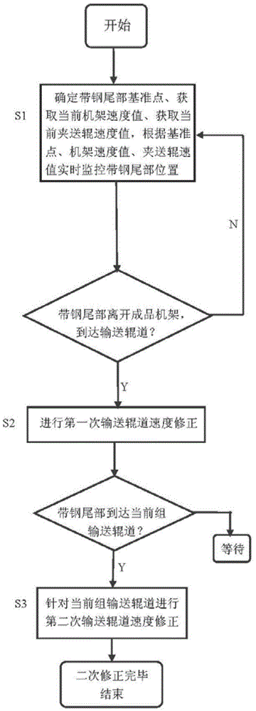
[0038] As shown in the figure, a method for controlling the speed of finishing rolling and throwing steel in a hot continuous rolling mill, the specific control technical scheme is as follows:

[0039] 1. Judging the position of the strip steel after throwing

[0040] Combined with the tail position tracking of the strip, the change of the rolling force of the stand is used as a condition in this technical solution to determine the specific position of the tail of the strip. The specific scheme is:

[0041] 1.1. Taking the rolling force signal of the rack as the judgment condition, judge the specific position of the tail of the strip, and use it as the reference point of the tail of the strip;

[0042] 1.2. After knowi...


PUM


Abstract

A method for controlling the finish rolling steel throwing speed of a hot continuous rolling mill adopts a rack speed detector, a clamping-delivering roller speed detector, a conveying roller way speed detector, a basic automatic level control machine and a process control machine to conduct speed reduction correction and segmented speed reduction control on the speed of a conveying roller way in a laminar cooling region between a finish rolling process and a coiling process according to set process requirement, specifically a secondary tracking and positioning mode is adopted for the speed reduction point control, a secondary correction mode is adopted for tail portion speed reduction control process to achieve indirect control of tensions of strip steel and the conveying roller way.

Description

technical field [0001] The invention belongs to the field of hot rolling process control, and in particular relates to a method for controlling the finishing rolling throwing speed of a hot continuous rolling mill. Background technique [0002] For the hot tandem rolling mill, the speed control of the finishing rolling and throwing involved directly affects the control of the coiling temperature, the quality of the strip coil shape, and the quality of the tail of the strip. For this reason, in the existing control technology, The running speed of the tail of the strip is controlled. In general, in the process of throwing thin strip steel, deceleration control is adopted, that is, a certain deceleration is used to control the speed of the tail of the strip. The basic The control is to set the deceleration in L2, and the running speed of the strip is decelerated at a certain deceleration, but in the actual production process on site, due to the deceleration on the running stri...

Claims


Application Information

Patent Timeline
Patent Type & Authority Applications(China)
IPC IPC(8): B21B37/46
CPCB21B37/46
Inventor 荣鸿伟周兴泽高志玲徐欣磊
Owner BAOSHAN IRON & STEEL CO LTD
Why Eureka
Try Eureka