Scissor type lifting tool for plate stacking

A spreader and stacking technology, which is applied in the field of scissor spreaders, can solve the problems of slipping slings, stacking thickness restrictions, and low work efficiency, so as to save stacking and bundling materials, eliminate loose stacking and stripping, and eliminate The effect of safety hazards

Active Publication Date: 2015-07-29
SHANGHAI DAZHONG XIANGYUAN POWER SUPPLY
View PDF13 Cites 5 Cited by
  • Summary
  • Abstract
  • Description
  • Claims
  • Application Information

AI Technical Summary

Problems solved by technology

[0002] At present, when lifting the stacks of plates (steel, plastic, plastic steel, glass, rubber, metal, wood, cardboard, fiber, etc.), the commonly used spreader is a sling; the stacks of plates need to be firmly bound before lifting , to prevent random stacking during the lifting process; during the lifting process of the sling, it is necessary to try the lifting many times to find the position of the center of gravity and a reasonable lifting point, and the lifting efficiency is low; in addition, the plate stacking is located between the two lifting points The part is concave due to the action of gravity, and it is easy to slip off the sling to cause a safety accident. Therefore, there is a limit to the thickness of the stack, and it cannot be lifted too much at one time; and for the semi-finished products that have been cut, it is easy to cause deformation and surface damage due to multiple clamping
[0003] Chinese patent CN203269320U discloses a scissor spreader, including a suspension ring, a first handle, a second handle, a first chain, a second chain and a self-locking device, the first chain and the second chain are connected to the suspension ring, the first The end of the handle is connected to the first chain, the end of the second handle is connected to the second chain, the middle part of the first handle and the second handle are hinged together to form a scissors structure, and the front ends of the first handle and the second handle are both There is a clamping part for clamping hole-type workpieces, and the self-locking device includes a lock hook installed on the second handle and a sawtooth on the first handle, so that by clamping the first handle and the front end of the second handle The part is inserted into the hole for lifting the workpiece to realize the lifting of the workpiece, but there are still some defects when lifting the stacked plates

Method used


Image

  • Scissor type lifting tool for plate stacking
  • Scissor type lifting tool for plate stacking
  • Scissor type lifting tool for plate stacking

Examples


Embodiment

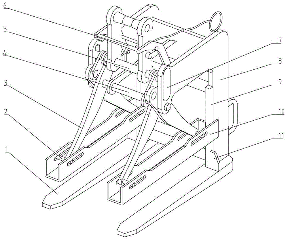
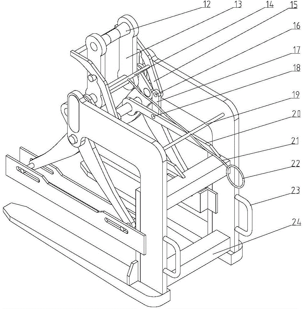
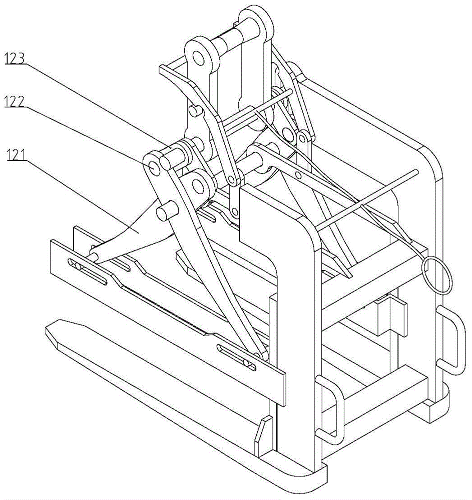
[0028] A scissor spreader for plate stacking, its structure is as follows Figure 1-3 As shown, it is composed of a scissor lever mechanism 3, a main frame, a locking device and a lifting rod. The scissor lever mechanism 3 is composed of two groups of left and right symmetrical linkage mechanisms. The fuselage 8 on the fuselage 1 is composed of the fuselage crosspiece 24 and the push-pull handle 23 arranged on the fuselage 8, and the junction of the fork-shaped bottom plate 1 and the fuselage 8 is also provided with a reinforcing rib 11. The locking device includes a locking bottom bar 20 connected to the top of the fuselage 8, a locking short connecting rod 17, a locking rod 15, an unlocking cable 21 and an unlocking pull ring 22, and the lifting rod 12 is arranged on the top of the fuselage 8 . Each constituent component will be further described in detail below.

[0029] The lower ends of two sets of scissor lever mechanisms 3 are installed in the chute of the groove-shap...


PUM


Abstract

The invention relates to a scissor type lifting tool for plate stacking. The scissor type lifting tool comprises a scissor type lever mechanism, a main frame, a locking device and a lifting rod, wherein the scissor type lever mechanism comprises two bilaterally symmetrical connecting rod mechanisms, the main frame comprises a fork-shaped bottom plate, a machine body connected onto the fork-shaped bottom plate as well as machine body crosspieces and push-pull handles which are arranged on the machine body, the locking device comprises bottom locking rods, short locking connecting rods, locking rods, a steel unlocking cable and an unlocking pull ring which are connected onto the upper side of the machine body, and the lifting rod is arranged at the top of the machine body. Compared with the prior art, the scissor type lifting tool has the advantages that the lifting tool is safe and reliable, the working efficiency is improved, the quality of semi-finished products is guaranteed and the like.

Description

technical field [0001] The invention relates to a sling, in particular to a scissor sling used for plate stacking. Background technique [0002] At present, when lifting the stacks of plates (steel, plastic, plastic steel, glass, rubber, metal, wood, cardboard, fiber, etc.), the commonly used spreader is a sling; the stacks of plates need to be firmly bound before lifting , to prevent random stacking during the lifting process; during the lifting process of the sling, it is necessary to try the lifting many times to find the position of the center of gravity and a reasonable lifting point, and the lifting efficiency is low; in addition, the plate stacking is located between the two lifting points The part is concave due to the action of gravity, and it is easy to slip off the sling to cause a safety accident. Therefore, there is a limit to the thickness of the stack, and it cannot be lifted too much at one time; and for the semi-finished products that have been cut, it is ea...

Claims


Application Information

Patent Timeline
IPC IPC(8): B66C1/22
CPCB66C1/22B66C1/42
Inventor 莫智敏唐峰
Owner SHANGHAI DAZHONG XIANGYUAN POWER SUPPLY
Why Eureka
Try Eureka