Novel warp knitting machine guide bar device

A warp knitting machine and bar technology, which is applied in the field of new warp knitting machine bar devices, can solve the problems of affecting the moving speed, low efficiency, and large friction area, so as to improve the moving speed and service life, and reduce maintenance costs , the effect of small contact area

Active Publication Date: 2015-07-29
汕头市荣昌实业有限公司
View PDF9 Cites 3 Cited by
  • Summary
  • Abstract
  • Description
  • Claims
  • Application Information

AI Technical Summary

Problems solved by technology

[0002] There are generally two kinds of comb bars used in traditional warp knitting machines. The earliest bar is made of aluminum material, but the aluminum bar is thick and benzene. The efficiency of the warp knitting machine using this bar is It is not high, and the startup speed is slow, which wastes a lot of electric energy; the other is the steel comb, which takes up a lot of space
[0003] And the copper bar is generally fixed on the existing comb bar, and the bar bar is inserted and sleeved in the copper bar to move, and the friction area between it and the copper bar is large, which affects the moving speed, and it is easy to wear the bar or the copper bar, affecting the speed of movement. service life
[0004] And the bar support block on the existing bar is fixed on the bar plate by bolts or welding, which is troublesome to disassemble

Method used


Image

  • Novel warp knitting machine guide bar device
  • Novel warp knitting machine guide bar device
  • Novel warp knitting machine guide bar device

Examples


Embodiment Construction

[0020] The present invention will be described in detail below in conjunction with accompanying drawings and specific preferred embodiments, so that the advantages and features of the present invention can be more easily understood by those skilled in the art. range is limited.

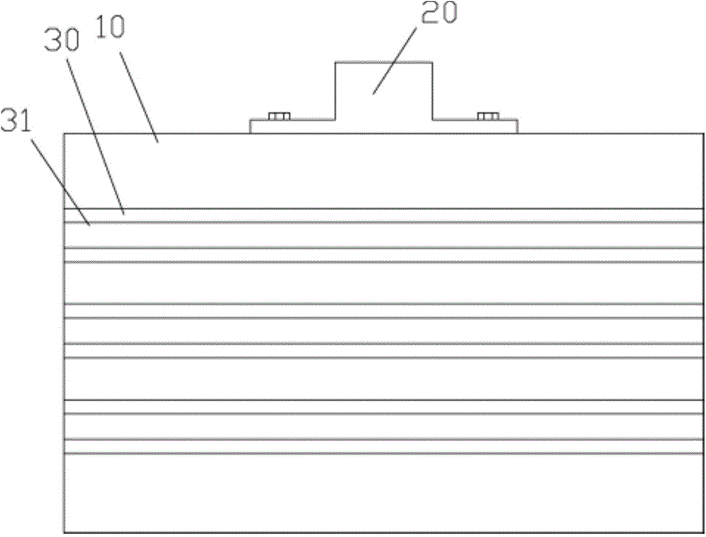
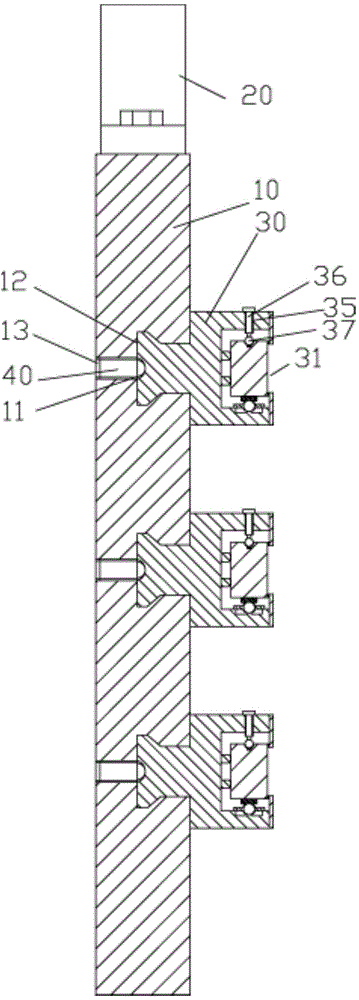
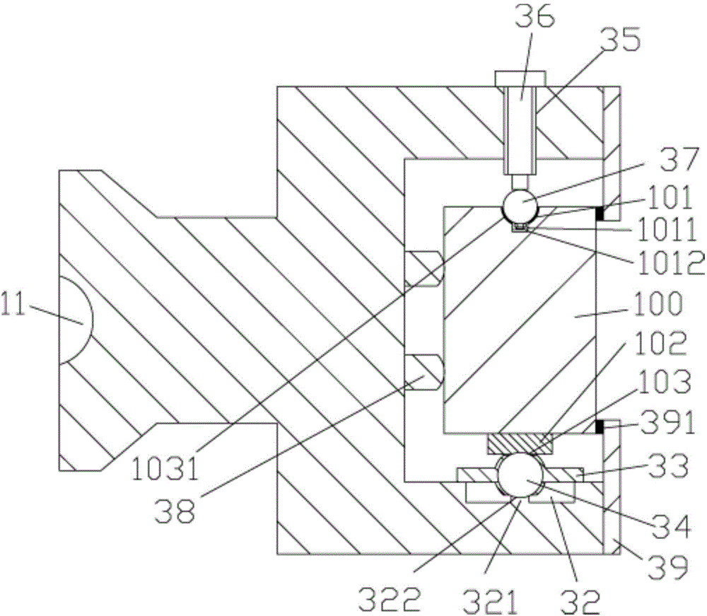
[0021] Examples, see e.g. Figure 1 to Figure 4 As shown, a novel warp knitting machine bar device includes a bar plate 10 and a bar bar 100, the top of the bar plate 10 is fixed with a support 20, and the side wall of the bar plate 10 has a plurality of transverse Slot 12, a plurality of comb strip support blocks 30 are inserted and sleeved in the slot 12, the back side of the comb plate 10 has a plurality of screw holes 13, the screw holes 13 communicate with the slot 12, and the ball plunger 40 is screwed on In the screw hole 13, the steel ball of the ball plunger 40 stretches into the slot 12 and is inserted in the concave hole 11 that is provided on the back wall surface of the bar bar support b...


PUM


Abstract

The invention discloses a novel warp knitting machine guide bar device. The novel warp knitting machine guide bar device comprises a guide bar plate and a plurality of guide bar strips, wherein a bracket is fixed to the top of the guide bar plate; a plurality of transverse inserting grooves are formed in the side wall of the guide bar plate; a plurality of guide bar strip supporting blocks are inserted into the inserting grooves; a plurality of screw holes are formed in the back surface of the guide bar plate and are communicated with the inserting grooves; ball plungers are connected to the screw holes in a screwing way; steel balls of the ball plungers extend into the inserting grooves and are inserted into concave holes in the back wall surfaces of the guide bar strip supporting blocks positioned in the inserting grooves; slide grooves are formed in the front wall surfaces of the guide bar strip supporting blocks; vertical screw holes are formed in the top surfaces of the slide grooves; adjusting bolts are screwed into the vertical screw holes; the top ends of the adjusting bolts press and push against the top surfaces of the guide bar strip supporting blocks; the bottom ends of the adjusting bolts extend into the slide grooves and are hinged to rolling balls; gliding grooves are formed in the bottom surfaces of the slide grooves. Each part of the novel warp knitting machine guide bar device can be detached, replaced and maintained, and meanwhile, during sliding of the device, the contact area is small and the friction force is low, so that the moving speed is increased, and the service life is prolonged.

Description

Technical field: [0001] The invention relates to the technical field of warp knitting machine equipment, and more specifically relates to a novel warp knitting machine bar device. Background technique: [0002] There are generally two kinds of comb bars used in traditional warp knitting machines. The earliest bar is made of aluminum material, but the aluminum bar is thick and benzene. The efficiency of the warp knitting machine using this bar is It is not high, and the startup speed is also slow, which wastes a lot of electric energy; the other is the steel bar, which takes up a lot of space. [0003] And the copper bar is generally fixed on the existing comb bar, and the bar bar is inserted and sleeved in the copper bar to move, and the friction area between it and the copper bar is large, which affects the moving speed, and it is easy to wear the bar or the copper bar, affecting the speed of movement. service life. [0004] And the bar support block on the existing bar i...

Claims


Application Information

Patent Timeline
Patent Type & Authority Applications(China)
IPC IPC(8): D04B27/24
Inventor 马根生
Owner 汕头市荣昌实业有限公司
Why Eureka
Try Eureka