Automatic wall plastering machine

A wall plastering and automatic technology, applied in the direction of construction, building structure, etc., can solve the problems of unstable column, difficult quality control, wall bulge, etc., to achieve convenient storage and assembly and disassembly, accurate and stable angle, reduce The effect of labor intensity

Inactive Publication Date: 2015-07-29
温宇辉
View PDF7 Cites 5 Cited by
  • Summary
  • Abstract
  • Description
  • Claims
  • Application Information

AI Technical Summary

Problems solved by technology

[0002] With the development of society, the quality requirements for plastering indoor walls are getting higher and higher. It is obviously impractical to achieve high-quality plastering work by hand. Manual plastering is not only time-consuming and labor-intensive, but also has high labor intensity, low efficiency and low It is difficult to control, and the wages of workers are increasing day by day, and the cost paid is increasing. Therefore, it is the general trend to replace manual plastering with machinery
[0003] Plastering with a wall plastering machine has the advantages of high efficiency, high quality, stability, and high degree of mechanization, but the wall plastering machines currently on the market have the following disadvantages: (1) The swing control of the push plate is controlled by two It is difficult to control the flatness of the top of the wall in this way, and it often causes the wall to bulge due to improper adjustment; (2) When adding materials, it is not possible to add enough mortar at one time. It is necessary to continuously add materials during the rising process of the machine, ther

Method used


Image

  • Automatic wall plastering machine
  • Automatic wall plastering machine
  • Automatic wall plastering machine

Examples


Embodiment Construction

[0030] The following will clearly and completely describe the technical solutions in the embodiments of the present invention with reference to the accompanying drawings in the embodiments of the present invention. Obviously, the described embodiments are only some, not all, embodiments of the present invention. Based on the embodiments of the present invention, all other embodiments obtained by persons of ordinary skill in the art without creative efforts fall within the protection scope of the present invention.

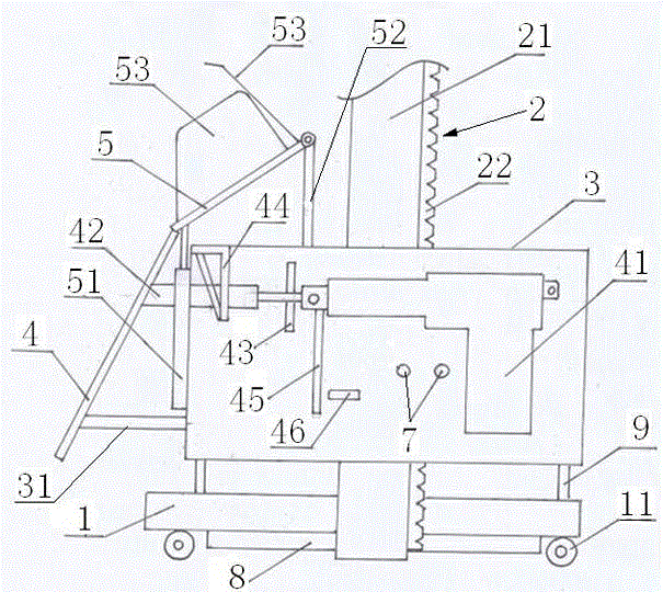
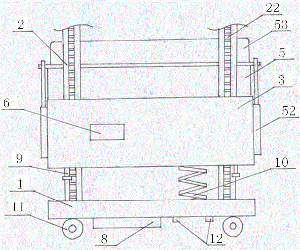
[0031] see in conjunction Figure 1 to Figure 4 As shown, an embodiment of an automatic wall plastering machine of the present invention includes a base 1, a column 2 vertically arranged on the base 1, a moving body 3 installed on the column 2, and the moving body 3 can The column 2 is used for the lifting movement of the track, and the front of the moving body 3 is provided with a push plate 4 .

[0032] The back of the push plate 4 is hinged with the front of th...


PUM


Abstract

The invention provides an automatic wall plastering machine. The automatic wall plastering machine comprises a base, an upright and a moving body; the moving body moves up and down on the upright as a track; a push plate is arranged on the frontage of the moving body and hinged to the front face; an electronic push rod and a first elastic telescopic rod are mounted on the two sides of the push plate; one end of the electronic push rod is fixed with the moving body, while the other end of the electronic push rod is hinged to one end of the first elastic telescopic rod; the other end of the first elastic telescopic rod is hinged to the back surface of the push plate; a material plate is mounted above the push plate; a second elastic telescopic rod and a third elastic telescopic rod are mounted on the two sides of the moving body correspondingly to the front and rear ends of the material plate, respectively; one end of the second elastic telescopic rod is hinged to the moving body, while the other end of the second elastic telescopic rod is hinged to the front end of the material plate; one end of the third elastic telescopic rod is fixed with the moving body, while the other end of the third elastic telescopic rod is hinged to the rear end of the material plate; an included angle is formed between the material plate and the upper surface of the moving body. The automatic wall plastering machine has the advantages of stable operation, good plastering effect, high automation degree, high applicability and the like.

Description

technical field [0001] The invention relates to the technical field of construction machinery, in particular to an automatic wall plastering machine. Background technique [0002] With the development of society, the quality requirements for plastering indoor walls are getting higher and higher. It is obviously impractical to achieve high-quality plastering work by hand. Manual plastering is not only time-consuming and labor-intensive, but also has high labor intensity, low efficiency and low It is difficult to control, and the wages of workers are also rising day by day, and the cost paid is increasing. Therefore, it is the general trend to replace manual plastering with machinery. [0003] Plastering with a wall plastering machine has the advantages of high efficiency, high quality, stability, and high degree of mechanization, but the wall plastering machines currently on the market have the following disadvantages: (1) The swing control of the push plate is controlled by ...

Claims


Application Information

Patent Timeline
IPC IPC(8): E04F21/08
Inventor 温宇辉
Owner 温宇辉
Why Eureka
Try Eureka