
Rubber compression roller device suitable for draw machine of polyester staple fiber post-treatment equipment

A technology of polyester staple fiber and rubber pressing roller, applied in mechanical equipment, rigid brackets of bearing components, bearing components, etc., can solve problems such as poor sealing effect, loose bearing axially fixed, bearing outer ring running circle, etc.

Active Publication Date: 2015-07-29
CHTC HEAVY IND +1
View PDF10 Cites 2 Cited by
  • Summary
  • Abstract
  • Description
  • Claims
  • Application Information

AI Technical Summary

Problems solved by technology

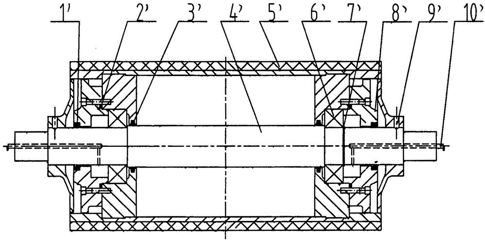
During its use, it is found that the sealing effect is not good, and water often enters the bearing cavity, which emulsifies the lubricating oil and damages the bearing; the O-ring is installed on the end face of the bearing end cover. To compress the outer ring of the bearing
In the production process, it is difficult to balance the two. It often happens that the axial fixation of the bearing is not tight, the outer ring of the bearing runs around, and the bearing is damaged, which affects the inner hole of the rubber roller.
In addition, the pressure roller rotates and the pressure roller shaft is fixed. The outer ring of the bearing and the inner hole of the rubber pressure roller need to adopt an interference fit, which is difficult to disassemble.

Method used


Image

  • Rubber compression roller device suitable for draw machine of polyester staple fiber post-treatment equipment
  • Rubber compression roller device suitable for draw machine of polyester staple fiber post-treatment equipment
  • Rubber compression roller device suitable for draw machine of polyester staple fiber post-treatment equipment

Examples


Embodiment Construction

[0014] The present invention will be further described below in conjunction with embodiment (accompanying drawing):

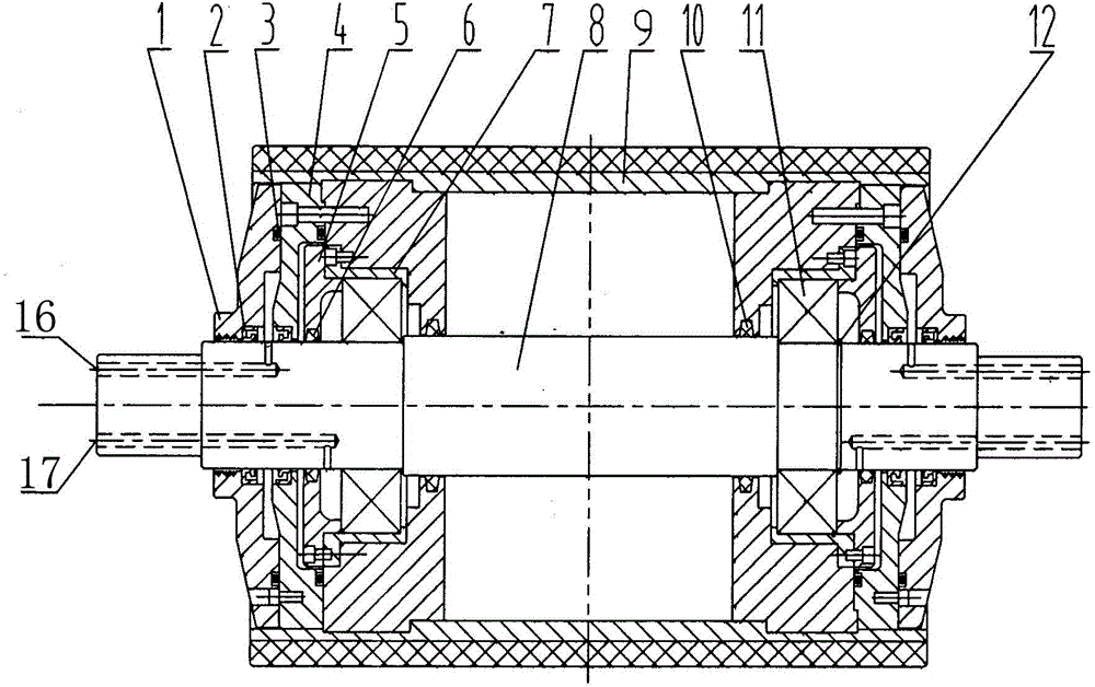
[0015] Such as figure 1 As shown, the rubber press roller device applicable to the drafting machine of polyester staple fiber post-processing equipment of the present invention includes a press roller shaft 8 combined with a rubber press roller 9 through a bearing 11; the bearing seat 7 for installing the bearing 11 is connected by The parts are fixedly installed in the shaft holes at both ends of the rubber pressure roller 9, the bearing 11 is sealed in the bearing seat 7 through the bearing end cover 5, and the inner ring of the bearing at the right end is fixed by the retaining ring 12 installed on the pressure roller shaft 8; Sealing felt rings are respectively installed in the ring grooves of the inner cylindrical surface of the bearing end cover 5 matched with the pressure roller shaft 8, and in the ring grooves of the inner cylindrical surface of the rub...


PUM


Abstract

The invention discloses a rubber compression roller device suitable for a draw machine of polyester staple fiber post-treatment equipment. The rubber compression roller device comprises a compression roller shaft combined with a rubber compression roller through bearings, wherein bearing seats used for mounting the bearings are fixedly mounted in shaft holes in two ends of the rubber compression roller through connecting pieces; the bearings are sealed in the bearing seats through bearing end covers; a sealing felt ring is mounted in each of an annular groove in the inner cylindrical surface of the bearing end cover matched with the compression roller shaft and an annular groove in the inner cylindrical surface of a rubber compression roller plug; a pressure cover is mounted on the outer end surface of the rubber compression roller plug through a connecting piece; an O-shaped seal ring is mounted between the seal fit surfaces of the pressure cover and the rubber compression roller plug; a skeleton seal ring is embedded into an annular groove in the inner cylindrical surface, matched with the compression roller shaft, of the pressure cover; a water throwing disc is mounted on the outer side of the pressure cover through a connecting piece; an O-shaped seal ring is mounted between the seal fit surfaces of the water throwing disc and the pressure cover; a skeleton seal ring is embedded into an annular groove in the inner cylindrical surface, matched with the compression roller shaft, of the water throwing disc.

Description

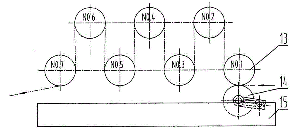
technical field [0001] The invention relates to a rubber pressing roller device of polyester staple fiber post-processing equipment, in particular to a rubber pressing roller device suitable for a drafting machine of polyester staple fiber post-processing equipment. Background technique [0002] The drafting machine of the polyester staple fiber post-processing equipment drafts the tow. The lower part of the drafting roller at the feeding end of the drafting machine is equipped with a rubber pressing roller device, on the one hand, to remove excess water, and on the other hand, to increase the grip of the tow, which is beneficial to the drafting process. A water tank is set under the pressure roller to work in an environment with a lot of moisture. Reliable bearing sealing is required to ensure the service life of the bearing. Pressure roller device in the prior art such as figure 1 . During its use, it is found that the sealing effect is not good, and water often enters...

Claims


Application Information

Patent Timeline
IPC IPC(8): F16C33/72F16C35/00
Inventor 韩宏亮张紫阳李新奇朱素娟乔光王航
Owner CHTC HEAVY IND
Learn More