A heat storage tank water distribution tray connection structure

A connection structure and water distribution tray technology, which is applied in the field of heat storage tank water distribution tray connection structure, can solve the influence of the space used inside the heat storage tank, the undisclosed upper water distribution tray installation structure, the undisclosed water distributor installation structure, etc. problems, to achieve the effect of improving spatial integrity and stability, meeting structural force requirements, and simple structure

Active Publication Date: 2016-10-12
HUADIAN ELECTRIC POWER SCI INST CO LTD
View PDF4 Cites 2 Cited by
  • Summary
  • Abstract
  • Description
  • Claims
  • Application Information

AI Technical Summary

Problems solved by technology

[0004] The key structure for the stratification of cold and hot water during the heat storage and release process of the heat storage tank is the water distribution plate. Since the capacity and diameter of the heat storage tank are relatively large, ordinary frame structures and other forms to support the water distribution plate will make the structure Complicated and uneconomical, the internal use space of the heat storage tank is affected
At present, there is no disclosure of a connection structure for heat storage tank water distribution trays with simple structure, reasonable design, good stability, and good economy. A heat exchange type process hot water heat storage system has been developed. The heat storage tank of the heat storage system is equipped with an upper and a lower water distributor respectively, and the specific installation structure of the water distributor has not been disclosed; another example is that the public date is 2015 On January 14, the Chinese patent with the publication number CN204100359U disclosed a direct heat storage system applied to the heat network. The specific installation structure of the upper water distribution tray

Method used


Image

  • A heat storage tank water distribution tray connection structure
  • A heat storage tank water distribution tray connection structure
  • A heat storage tank water distribution tray connection structure

Examples


Embodiment Construction

[0027] The present invention will be further described in detail below in conjunction with the accompanying drawings and examples. The following examples are explanations of the present invention and the present invention is not limited to the following examples.

[0028] Example.

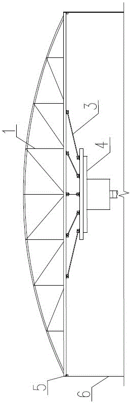
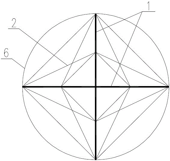
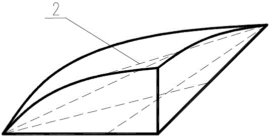
[0029] see Figure 1 to Figure 6 , the heat storage tank water distribution pan connection structure in this embodiment includes a heat storage tank water distribution pan 4, two truss structures 1 for sharing the weight of the heat storage tank water distribution pan 4, and two truss structures 1 for enhancing the stability of the truss structure 1 Truss reinforcement members 2, at least three water distribution pan suspension structures 3 for transferring the weight of the heat storage tank water distribution pan 4, and four for fixing the truss structure 1 to the upper inner wall 6 of the heat storage tank and supporting the truss structure 1 The supporting truss supports the connecting structu...


PUM


Abstract

The invention relates to a thermal storage tank water distribution plate connecting structure which is simple in structure, reasonable in design and fine in stability and economical efficiency. The thermal storage tank water distribution plate connecting structure is characterized by comprising a thermal storage tank water distribution plate, at least two truss structures, truss reinforcement components, at least three water distribution plate suspension structures and at least four truss support connecting structures, the truss structures are used for sharing the weight of the thermal storage tank water distribution plate, the truss reinforcement components are used for reinforcing stability of the truss structures, the water distribution plate suspension structures are used for transferring the weight of the thermal storage tank water distribution plate, the truss support connecting structures are used for fixing the truss structures to the upper inner wall of a thermal storage tank, each truss structure comprises an upper chord member, a lower chord member, a plurality of vertical rods and a plurality of diagonal web members, two ends of each diagonal web member are fixed onto the corresponding upper chord member and the corresponding lower chord member, water distribution plate lifting lugs are fixed onto a top plate of the thermal storage tank water distribution plate, the truss support connecting structures are fixed onto the upper inner wall of the thermal storage tank, and two ends of each truss structure are fixed onto the corresponding truss support connecting structure. The thermal storage tank water distribution plate connecting structure is fine in stability and economical efficiency.

Description

technical field [0001] The invention relates to a connection structure of a water distribution pan of a heat storage tank, which uses welding and bolt connection to lift the water distribution pan of the heat storage tank, and transmits the weight of the water distribution pan to the basic connection structure through an intermediate force transmission structure. Background technique [0002] At present, the main problems in the adjustment method of the first station of the heating network in the heating system are: first, the thermal inertia of the large heating network system is relatively large, and it takes a long time for the first station to adjust the heat to the terminal building, and the adjustment period is long. The first station usually actively adjusts the load once or twice a day, and sometimes even does not adjust for a few days, which lags behind the load demand and does not match the actual situation; however, due to factors such as ambient temperature and so...

Claims


Application Information

Patent Timeline
Patent Type & Authority Patents(China)
IPC IPC(8): F28D20/00
CPCY02E60/14
Inventor 徐朝阳孙士恩俞聪赵明德何晓红
Owner HUADIAN ELECTRIC POWER SCI INST CO LTD
Why Eureka
Try Eureka