
Z-axis driving connection mechanism of nozzle rod of SMT system

A technology of suction and drive connection of a placement machine, which is applied to electrical components, electrical components, etc., can solve the problems affecting the accuracy of the nozzle rod assembly, restricting the miniaturization of the placement head, and the hardness of the nozzle rod, etc., to achieve miniaturization. , Fast installation, and the effect of reducing friction

Active Publication Date: 2017-12-26
浙江华企正邦自动化科技有限公司
View PDF12 Cites 2 Cited by
  • Summary
  • Abstract
  • Description
  • Claims
  • Application Information

AI Technical Summary

Problems solved by technology

From the above, it can be seen that the current connection structure between the nozzle rod and the lower platen has the following problems: 1. It is difficult to install and the installation accuracy is difficult to control, because the axis line of the bearing fixing hole and the nozzle rod must be on the same axis to ensure Mounting accuracy; 2. The size of the lower platen will restrict the development of the miniaturization of the placement head
At present, there are the following problems in domestic nozzle rods with splined rods: if the structure of the nozzle rod is processed to improve the hardness of the material, the nozzle rod will be deformed, which will seriously affect the accuracy of the nozzle rod assembly; if the nozzle rod is removed first Improve the hardness of the material, and the improved nozzle rod will not be able to be processed because the hardness is too hard
Therefore, if you want to enhance the wear resistance of the nozzle rod and prolong the service life of the nozzle rod, at present, this type of nozzle rod can only rely on imports, and the price is expensive

Method used


Image

  • Z-axis driving connection mechanism of nozzle rod of SMT system
  • Z-axis driving connection mechanism of nozzle rod of SMT system
  • Z-axis driving connection mechanism of nozzle rod of SMT system

Examples


Embodiment Construction

[0034] The present invention will be further described below in conjunction with the accompanying drawings.

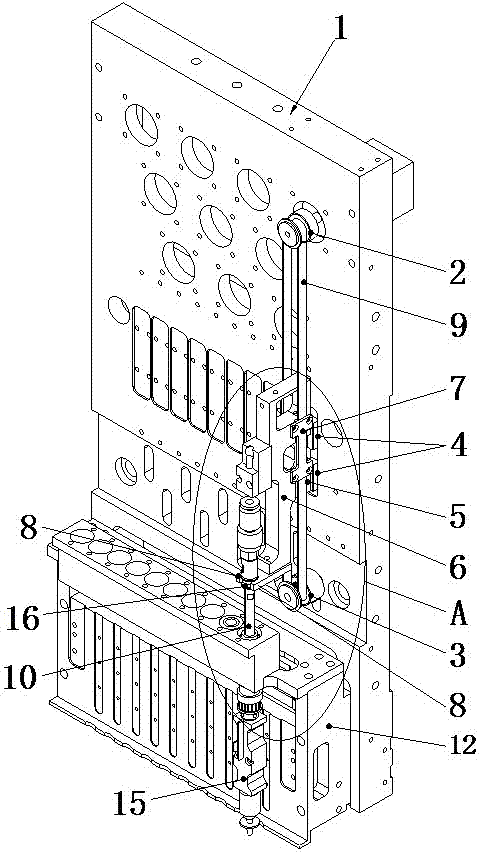
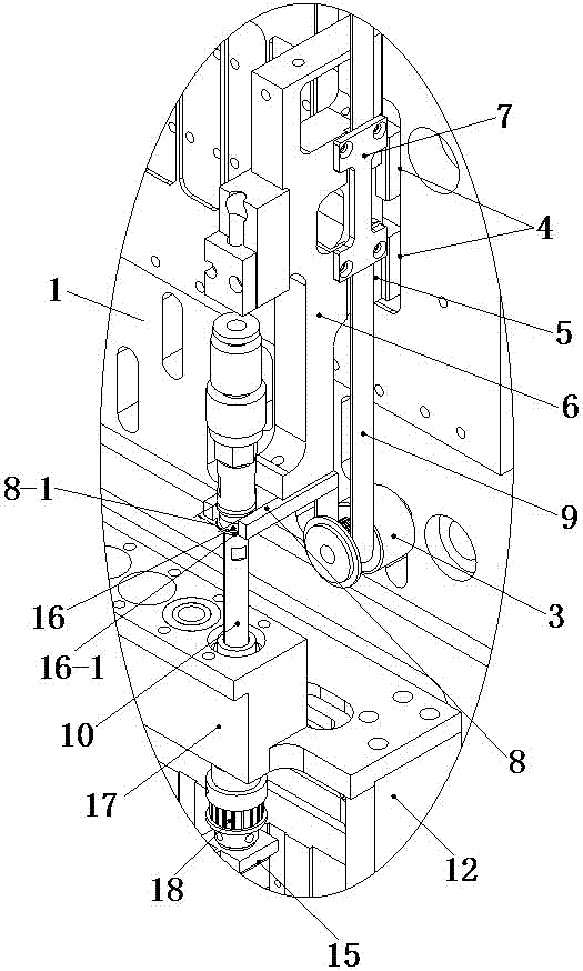
[0035] Such as Figure 1 to Figure 3 As shown, the suction nozzle rod of a chip mounter according to the present invention drives the connection mechanism in the Z-axis direction, including a Z-axis pressing motor (not shown in the figure), a motor pulley 2, a driven pulley 3, a Z The shaft belt 9 and the suction nozzle rod 10, the surface of the mounting head fixed substrate 1 is provided with a motor installation through hole matching the Z-axis pressing motor, and one end of the rotating shaft of the Z-axis pressing motor passes through the motor installation through hole A motor pulley 2 is fixedly connected, and a driven pulley 3 matching the motor pulley 2 is also provided on the surface of the mounting head fixed substrate 1; the motor pulley 2 is connected with the driven pulley 3 through a Z-axis belt 9. The spline rod section of the suction nozzle rod 10 is ...


PUM


Abstract

The invention relates to the technical field of SMT (surface mount technology) systems, in particular to a Z-axis driving connection mechanism of a nozzle rod of an SMT system. The Z-axis driving connection mechanism comprises a press-down linkage plate, the surface of a surface mount head fixing base plate is fixedly connected with the press-down linkage plate through a guide mechanism, one end of a nozzle rod press plate is fixedly arranged at the bottom end of the press-down linkage plate, the nozzle rod press plate is connected with the nozzle rod through a bearing component consisting of flange bearings, and a nozzle rod sleeve is connected to the outer circumferential wall of the nozzle rod through a rod sleeve bearing. One end of a slidable fixed frame is fixedly arranged on the surface of the surface mount head fixing base plate while the other end thereof is connected with the nozzle rod through a slide mechanism body, and the nozzle rod sleeve is capable of sliding on the slide mechanism body along the length direction of the nozzle rod. The Z-axis driving connection mechanism has the advantages that miniaturization of the SMT system is facilitated, mounting is facilitated to reduce production cost of a surface mount head, and surface mount precision is guaranteed enduringly.

Description

technical field [0001] The invention relates to the technical field of SMT placement machines, in particular to a driving connection mechanism for a suction nozzle rod of a placement machine in the Z-axis direction. Background technique [0002] The suction nozzle rod of the SMT placement machine mainly moves in four directions, namely the X-axis direction movement, the Y-axis direction movement, the Z-axis direction movement and the R-axis direction movement; among them, the X-axis direction movement refers to the movement of the entire group of nozzle rods The horizontal (longitudinal) movement parallel to the horizontal plane under the fixation of the placement head, the movement in the Y-axis direction refers to the longitudinal (horizontal) movement of the entire set of nozzle rods parallel to the horizontal plane under the fixation of the placement head; the Z-axis direction Movement refers to the movement of the nozzle rod in a direction perpendicular to the horizonta...

Claims


Application Information

Patent Timeline
Patent Type & Authority Applications(China)
IPC IPC(8): H05K13/04
CPCH05K13/0408
Inventor 梁文灿李清国
Owner 浙江华企正邦自动化科技有限公司
Learn More