
Electromagnetic force density transferring method used among special-shaped grids in magnetic field-structure field coupling calculation

A technology of structural field and electromagnetic force, which is applied in computing, electrical digital data processing, special data processing applications, etc., can solve the problem of different grid division accuracy and shape, improve calculation time and accuracy, and reduce the number of grids Effect

Inactive Publication Date: 2015-07-29
CHINA THREE GORGES UNIV
View PDF3 Cites 4 Cited by
  • Summary
  • Abstract
  • Description
  • Claims
  • Application Information

AI Technical Summary

Problems solved by technology

[0004] The technical problem to be solved by the present invention is to provide an electromagnetic force density transfer method between special-shaped grids in the magnetic field-structure field coupling calculation, and propose a special-shaped grid data transfer method to process the overall finite element model in the magnetic field-structure field coupling calculation The problem of electromagnetic force density transmission between grids caused by inconsistency solves the problem of different requirements for grid subdivision accuracy and shape of magnetic field and structural field, and can realize the transmission of electromagnetic force density between different types of grids for magnetic field and structural field, greatly Reduce the number of grids, improve the calculation time and accuracy

Method used


Image

  • Electromagnetic force density transferring method used among special-shaped grids in magnetic field-structure field coupling calculation
  • Electromagnetic force density transferring method used among special-shaped grids in magnetic field-structure field coupling calculation
  • Electromagnetic force density transferring method used among special-shaped grids in magnetic field-structure field coupling calculation

Examples


Embodiment

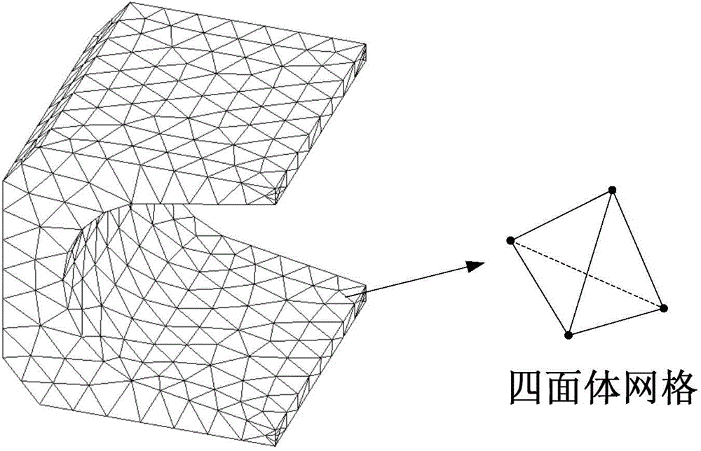
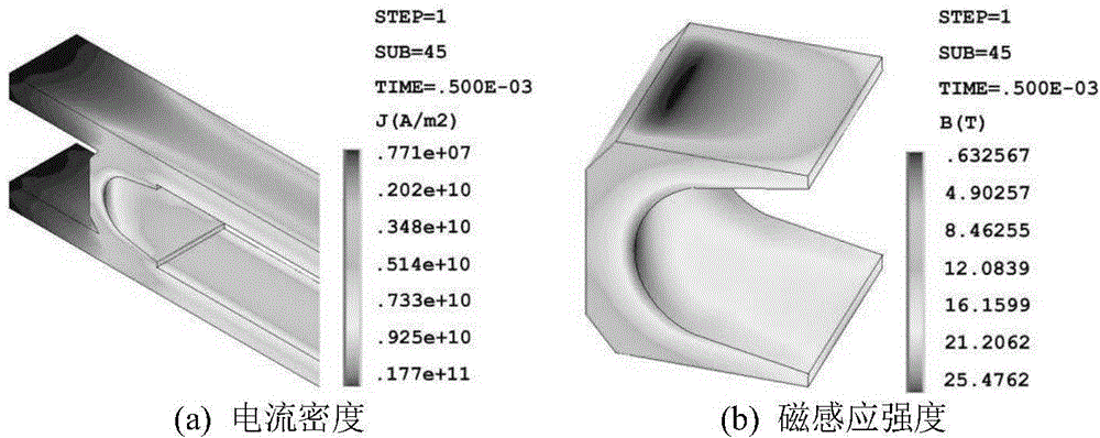
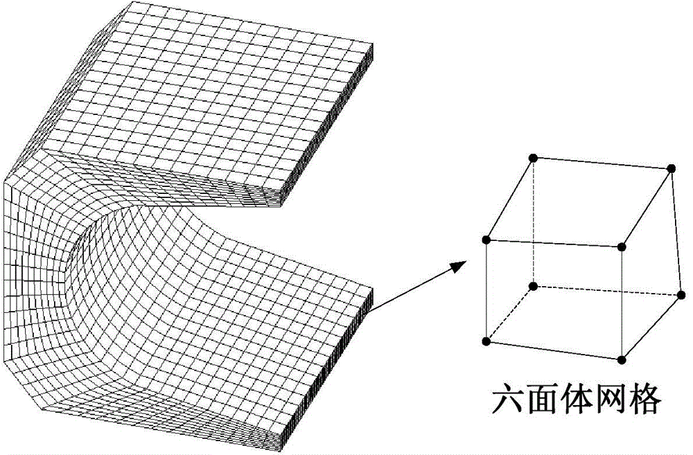
[0039] Taking the electromagnetic track launcher as an example, the numerical calculation of the magnetic field-structure field indirect coupling is carried out. The geometric dimensions of the armature like image 3 As shown, the magnetic field grid Figure 1 (a), Structure field mesh Figure 1 (b), the material parameters of the armature as table 1 As shown, the pulse current applied to the rail like Figure 4 shown. Calculate the distribution of current density J and magnetic induction B like Figure 5 As shown, according to the present invention, the electromagnetic force density transmission method is proposed, and the grid number 1-10 is selected as an example, and the coordinates of the center of gravity and the calculated components of the electromagnetic force density f in the x, y, and z directions as table 2 shown.

[0040] Table 1

[0041]

[0042] Table 2

[0043]


PUM


Abstract

The invention discloses an electromagnetic force density transferring method used among special-shaped grids in magnetic field-structure field coupling calculation. The electromagnetic force density transferring method comprises the following steps: an electromagnetic field calculation finite element model is built; the shapes and the sizes of the grids are determined according to the magnetic field distribution characters of research objects; magnetic field numerical calculation on the research objects is preformed to obtain the current density J and the magnetic induction intensity B of each unit respectively; a geometric model of the research objects in the structural field calculation is re-built again; the model is discretized into finite element girds, wherein the shapes and the sizes of the finite element grids are different from those of an electromagnetic field; the coordinates Mi (xi i, eta i, zeta i) of the gravity center of each unit of the finite element model in a structure field are read; corresponding points Mi' (xi, yi, zi) of the gravity center of each unit in the structure field are found according to the coordinate values; the J and B of the Mi' (xi, yi, zi) are obtained by interpolating; electromagnetic force density f at each point is obtained based on a formula that f is equal to J*B; the f value of each gravity center point is read to be used as load to be applied to each unit in the structure field for calculation to obtain a stress distribution result. The data transmission among the grids of different types can be realized in the magnetic field and the structure field; the calculation time is shortened and the calculation precision is improved.

Description

technical field [0001] The invention relates to a data transmission method between finite element grids, in particular to an electromagnetic force density transmission method between special-shaped grids in magnetic field-structure field coupling calculation. Background technique [0002] The basic steps of the finite element numerical calculation of the magnetic field-structure field based on the indirect coupling solution method are as follows: ① Firstly, the current density J and the magnetic induction intensity B of each unit are obtained through the finite element calculation of the magnetic field. The Lorentz force f can be obtained by the formula It is obtained by solving f=J×B; ②Apply f as a load to the structure field; ③Finally, the stress-strain distribution is obtained through the finite element calculation of the structure field. In this solution process, the electromagnetic force density transfer from the magnetic field to the structural field finite element gri...

Claims


Application Information

Patent Timeline
IPC IPC(8): G06F17/50
Inventor 张宇娇秦威南黄雄峰
Owner CHINA THREE GORGES UNIV
Learn More