Pneumatic blowing-in optical fiber composite smart energy power cable and production method thereof

A power cable and optical fiber composite technology, used in power cables, power cables with shielding/conducting layers, cable/conductor manufacturing, etc., can solve problems affecting optical communication quality, optical attenuation, etc. The effect of convenient later use and maintenance and convenient fiber replacement

Inactive Publication Date: 2015-07-29
FAR EAST CABLE +2
View PDF7 Cites 7 Cited by
  • Summary
  • Abstract
  • Description
  • Claims
  • Application Information

AI Technical Summary

Problems solved by technology

Every connection of optical fiber will cause light attenuation, which will affect the quality of optical communication.

Method used


Image

  • Pneumatic blowing-in optical fiber composite smart energy power cable and production method thereof
  • Pneumatic blowing-in optical fiber composite smart energy power cable and production method thereof

Examples


Embodiment 1

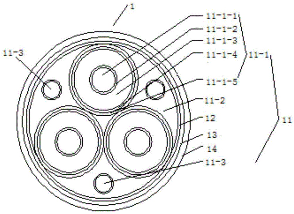
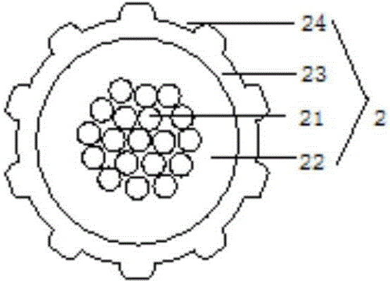
[0032] See figure 1 and figure 2 , the pneumatic blowing type optical fiber composite smart energy power cable of this embodiment is composed of a power cable 1 embedded in the optical unit tube and a transmission optical fiber unit 2; the power cable 1 embedded in the optical unit tube is the cable from the inside to the outside Core 11, inner lining layer 12, armor layer 13 and outer sheath 14; cable core 11 includes three insulated cores 11-1 and three fillers 11-2; insulated cores 11-1 are conductors from inside to outside 11-1-1, conductor shielding layer 11-1-2, insulating layer 11-1-3, insulating shielding layer 11-1-4 and metal shielding layer 11-1-5; three light beams are arranged in filling 11-2 The unit tube 11-3; the transmission fiber unit 2 includes an optical fiber 21, a solidified layer 22, a sheath 23 and ten pressure channels 24 arranged on the surface of the sheath 23; the transmission fiber unit 2 is suspended in the optical unit tube 11- of the power cab...


PUM

PropertyMeasurementUnit
thicknessaaaaaaaaaa

Abstract

The invention discloses a pneumatic blowing-in optical fiber composite smart energy power cable and a production method thereof. The cable is composed of power cable bodies of embedded optical unit tubes and transmission optical fiber units. Every power cable body of the embedded optical unit tube is sequentially composed of a cable core, an inner lining layer, an armor layer and an outer sheath from inside to outside. The cable core comprises at least one insulation cable core body and filling. The insulation cable core body is sequentially composed of a conductor, a conductor shielding layer, an insulating layer, an insulating shielding layer and a metal shielding layer from inside to outside. The filling is internally provided with at least one optical unit tube. The number of the transmission optical fiber units is the same with that of the optical unit tubes. Every transmission optical fiber unit comprises an optical fiber, a cured layer, a protective layer and at least one pressure channel arranged on the surface of the protective layer. The transmission optical fiber units are suspended in the optical unit tubes of the power cable bodies. The pneumatic blowing-in optical fiber composite smart energy power cable is produced through an on-site compositing mode, and accordingly the cable is divided into two parts of the cable bodies of the embedded optical unit tubes and the transmission optical fiber units, so that the problems of power cable length loss, optical fiber communication performance degradation and the like of an existing optical fiber composite power cable composite cable in construction and installation is solved.

Description

technical field [0001] The invention relates to an optical fiber composite power cable, in particular to a pneumatic blown type optical fiber composite smart energy power cable and a manufacturing method thereof. Background technique [0002] Optical fiber composite power cable is a new type of optical fiber composite cable used in power lines. It has the functions of ordinary cable, communication optical cable and online detection. Carry out services such as "three-network integration" of telecommunications network, broadcasting network, and Internet content transmission, combined with online monitoring power network construction, and finally realize the construction of a strong and intelligent large power grid. [0003] At present, optical fiber composite power cables are also published in patent documents, such as the utility model patent ZL201120092927.4 "An Optical Fiber Composite Medium Voltage Cable", which has a structure including a cable core, a cable core tape lay...

Claims


Application Information

Patent Timeline
Patent Type & Authority Applications(China)
IPC IPC(8): H01B9/00H01B9/02H01B13/00G02B6/44
Inventor 陆正荣张右王秀琳黄敏建周锋路文贤王艳洁元巍陈东
Owner FAR EAST CABLE
Why Eureka
Try Eureka