A coupling structure terahertz directional coupler

A technology of directional coupler and coupling structure, which is applied to waveguide-type devices, electrical components, connecting devices, etc., can solve the problem of inability to meet the transmission characteristics of terahertz wave transmission lines, surface accuracy and shape and position tolerance requirements are getting higher and higher, performance indicators It is difficult to obtain guarantee and other problems, so as to reduce the processing difficulty and cost, reduce the requirements of dimensional tolerance, and reduce the difficulty and cost.

Active Publication Date: 2018-01-30
THE 41ST INST OF CHINA ELECTRONICS TECH GRP
View PDF4 Cites 0 Cited by
  • Summary
  • Abstract
  • Description
  • Claims
  • Application Information

AI Technical Summary

Problems solved by technology

The use of laser technology is also a method of processing the coupling sheet, but whether the control of the dimensional accuracy of laser processing and the control of shape and position tolerances such as roundness can meet the design requirements requires a long period of exploration and testing.
[0005] At present, small hole coupling is often used in the terahertz band. As the frequency becomes higher and higher, the size of the coupling hole becomes smaller and smaller, and the requirements for surface accuracy and shape and position tolerance become higher and higher, and the processing difficulty is high. Low, at the same time performance indicators are difficult to be guaranteed
Using a drilling machine for fitter drilling, using slow wire cutting for electric cutting and laser drilling to process coupling holes is costly, and the precision of the processed holes is not high, and material accumulation will form around the holes, which cannot meet the requirements of terahertz waves. Requirements for the transmission characteristics of transmission lines

Method used


Image

  • A coupling structure terahertz directional coupler
  • A coupling structure terahertz directional coupler
  • A coupling structure terahertz directional coupler

Examples


Embodiment Construction

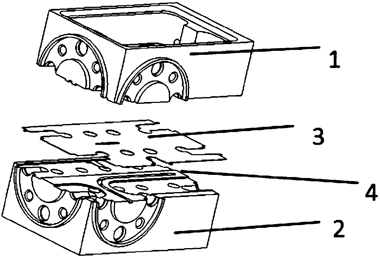
[0024] The present invention will be further described below in conjunction with the accompanying drawings and embodiments.

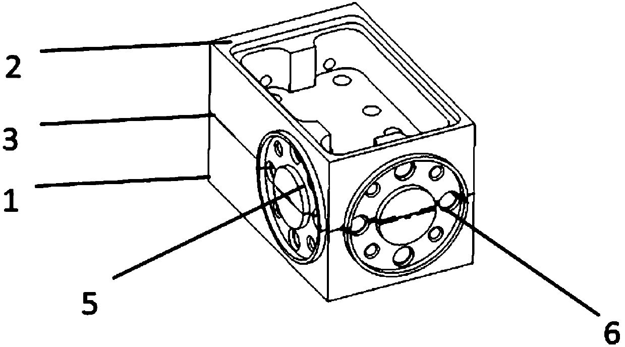
[0025] Terahertz directional couplers are key devices for signal incidence, reflection and transmission, and are widely used in radar, radiometer, imaging, astronomical observation, environmental detection and security inspection. How to solve the flatness and broadband characteristics of the coupler, as well as the processability and ease of realization in the special frequency band of terahertz, are the primary problems faced by the terahertz directional coupler.

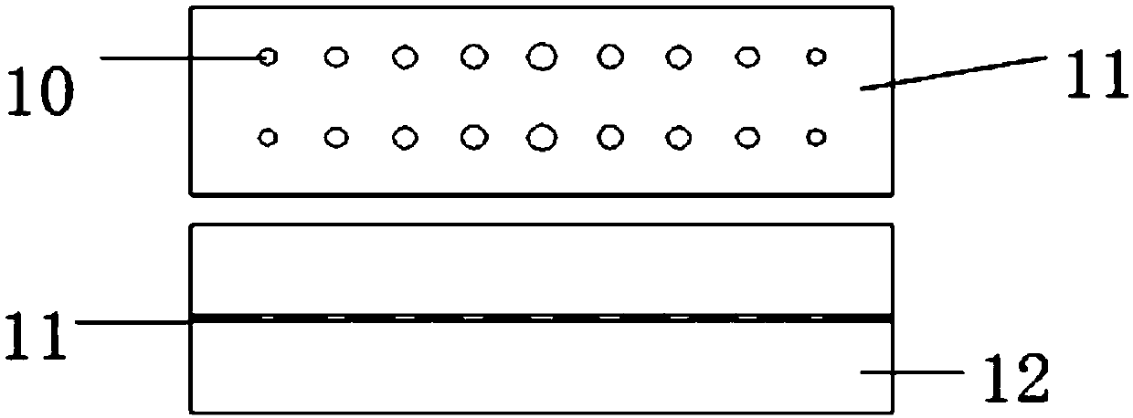
[0026] In the terahertz band, coupling methods such as circular hole coupling, elliptical hole coupling, cross hole coupling and rectangular hole coupling are often used. As the frequency becomes higher and higher, the size of the coupling hole becomes smaller and smaller, which affects the surface accuracy and shape tolerance. The requirements are getting higher and higher, the processing ...


PUM


Abstract

The invention discloses a terahertz directional coupler with a coupling structure, which includes an upper chamber, a lower chamber and a coupling plate. The upper chamber has a straight-through groove, the lower chamber has a coupling groove, and the coupling plate does not have any grooves. "Coupling hole; among them, the connection between the upper cavity and the coupling plate constitutes a straight-through path, and the connection between the coupling plate and the lower cavity forms a coupling branch, which provides input power to the input port and is coupled through the "eye-pattern" coupling hole, and a part of the power is transmitted to the coupling port , while the rest of the power is directly transmitted from the input port to the output port; in view of the current terahertz directional coupler's relatively large tolerance, high processing and assembly precision requirements, and difficult to guarantee the surface quality of the coupling plate, the "eye pattern" is proposed in the design. The coupling structure ensures the flatness and wide frequency band of the coupler, reduces the requirements for relative tolerance and assembly accuracy, reduces the difficulty and cost of processing, and makes the designed components more producible.

Description

technical field [0001] The invention relates to a coupling structure terahertz directional coupler. Background technique [0002] Terahertz directional couplers are key devices for signal incidence, reflection and transmission, and are widely used in radar, radiometer, imaging, astronomical observation, environmental detection and security inspection. How to solve the flatness and broadband characteristics of the coupler, as well as the processability and ease of realization in the special frequency band of terahertz, are the primary problems faced by the terahertz directional coupler. [0003] In the terahertz band, coupling methods such as circular hole coupling, elliptical hole coupling, cross hole coupling and rectangular hole coupling are often used. As the frequency becomes higher and higher, the size of the coupling hole becomes smaller and smaller, which affects the surface accuracy and shape tolerance. The requirements are getting higher and higher, the processing ...

Claims


Application Information

Patent Timeline
Patent Type & Authority Patents(China)
IPC IPC(8): H01P5/18
Inventor 陈卓邓建钦年夫顺姜万顺
Owner THE 41ST INST OF CHINA ELECTRONICS TECH GRP
Why Eureka
Try Eureka