
Objective evaluation method for stereo image visual comfort degree

An objective evaluation method, stereo image technology, applied in stereo systems, image communication, television, etc., can solve problems such as conflict, visual fatigue, conflict vision of vergence mechanism, etc.

Active Publication Date: 2015-07-29
郎溪品旭科技发展有限公司
View PDF4 Cites 17 Cited by
  • Summary
  • Abstract
  • Description
  • Claims
  • Application Information

AI Technical Summary

Problems solved by technology

However, excessive binocular parallax, human eye focus adjustment, and convergence mechanism conflicts are generally considered to be the main causes of visual discomfort
The binocular fusion mechanism of the human eye provides a physiological guarantee for the fusion of the left and right eye images with horizontal parallax into a single clear object image with stereoscopic effect. However, if the horizontal parallax is too large, the object image will fall outside the Panum fusion area , the human eye will not be able to form binocular single vision normally, and it will easily cause severe visual fatigue when watching for a long time; in addition, it is different from the consistency of the focus adjustment and convergence mechanism of the human eye under natural viewing conditions (both the adjustment distance and the convergence distance are viewed on the screen) above), when viewing stereoscopic images, the focus adjustment and convergence mechanism of the human eye will produce different degrees of conflict, which will also affect the visual experience quality of the viewer

Method used


Image

  • Objective evaluation method for stereo image visual comfort degree
  • Objective evaluation method for stereo image visual comfort degree
  • Objective evaluation method for stereo image visual comfort degree

Examples


Embodiment Construction

[0037] The present invention will be further described in detail below in conjunction with the accompanying drawings and embodiments.

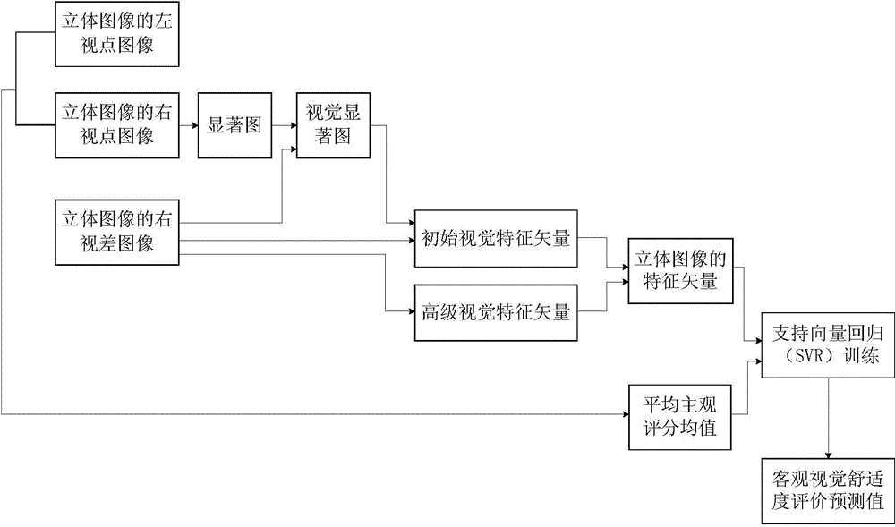
[0038] An objective evaluation method for visual comfort of stereoscopic images proposed by the present invention, its overall realization block diagram is as follows figure 1 As shown, it includes the following steps:

[0039] ① Denote the left viewpoint image of the stereoscopic image to be evaluated as {I L (x, y)}, denote the right viewpoint image of the stereo image to be evaluated as {I R (x,y)}, denote the right disparity image of the stereo image to be evaluated as {d R (x, y)}, where (x, y) represents the coordinate position of the pixel in the stereoscopic image to be evaluated, 1≤x≤W, 1≤y≤H, and W represents the coordinate position of the stereoscopic image to be evaluated Width, H represents the height of the stereoscopic image to be evaluated, I L (x,y) means {I L The pixel value of the pixel whose coordinate position is (x, ...


PUM


Abstract

The invention discloses an objective evaluation method for a stereo image visual comfort degree. The objective evaluation method for the stereo image visual comfort degree includes: firstly, extracting a primary visual feature vector and a senior visual feature vector of a right parallax image of the stereo image used to reflect a visual comfort degree, and fusing the primary visual feature vector and the senior visual feature vector so as to obtain a feature vector of the stereo image, secondly, using a support vector regression to train feature vectors of all stereo images in a stereo image collection, and finally, using a support vector regression training model obtained from trainings to test a feature vector of each stereo image in the stereo image collection, and obtaining an objective visual comfort degree evaluation prediction value of each stereo image. The objective evaluation method for the stereo image visual comfort degree has the advantages that the feature vector of the stereo image obtained according to the primary visual feature vector and the senior visual feature vector of the right parallax image of the stereo image has strong stability, and visual comfort degree changing conditions of the stereo image can be reflected well, and therefore correlations between objective evaluation results and subjective perception are effectively improved.

Description

technical field [0001] The invention relates to an image quality evaluation method, in particular to an objective evaluation method for stereoscopic image visual comfort. Background technique [0002] With the rapid development of stereoscopic video display technology and high-quality stereoscopic video content acquisition technology, the visual quality of experience (QoE, Quality of Experience) of stereoscopic video is an important issue in the design of stereoscopic video systems, and visual comfort (VC, Visual Comfort) is an important factor affecting the visual experience quality of stereoscopic video. At present, the research on the quality evaluation of stereoscopic video / stereoscopic images mainly considers the influence of content distortion on image quality, but rarely considers the influence of factors such as visual comfort. Therefore, in order to improve the visual experience quality of viewers, it is very important to study the objective evaluation model of vis...

Claims


Application Information

Patent Timeline
IPC IPC(8): H04N17/00H04N13/00
Inventor 邵枫姜求平李福翠
Owner 郎溪品旭科技发展有限公司
Learn More