Medical Electric Transfer Vehicle

A transfer vehicle, electric technology, applied in the direction of medical transportation, transportation and packaging, vehicle rescue, etc., can solve the problems of increasing the labor intensity of medical staff and family members, and causing pain to patients, so as to achieve ingenious structural design and avoid secondary Pain, comfort and safety effects

Active Publication Date: 2017-04-26
田永建 +3
View PDF9 Cites 0 Cited by
  • Summary
  • Abstract
  • Description
  • Claims
  • Application Information

AI Technical Summary

Problems solved by technology

[0003] The purpose of the present invention is to solve the technical problems that the medical stretcher trolley in the prior art is easy to bring pain to the patient and increase the labor intensity of the medical staff and family members in the process of changing the bed, and to provide a reasonable structural design, easy to use, A medical electric transfer vehicle that can reduce the pain of changing beds for patients and reduce the work intensity of medical staff

Method used


Image

  • Medical Electric Transfer Vehicle
  • Medical Electric Transfer Vehicle
  • Medical Electric Transfer Vehicle

Examples


Embodiment 1

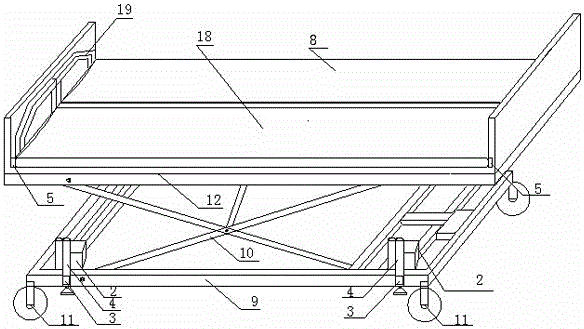
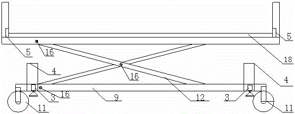
[0025] For the medical electric transfer vehicle of this embodiment, refer to the attached Figure 1-7 , including a lifting mechanism for driving the vehicle panel frame 12 up and down, a balance outrigger motor 2, a balance outrigger 3, a balance push rod motor 4, two vehicle panel telescopic arms 5, a vehicle panel drive motor 6, and a vehicle panel drive arm 7 , the front panel 8, the rear panel 18, two vertical baffles 19, the chassis frame 9, the four central control casters 11 of the vehicle frame lifting arm 10, which are located at the two ends of the front panel 8 and the rear panel 18 in the length direction , car panel frame 12, car panel turning device, turning motor 14, central control caster pedal 15, 6 connecting shafts 16, 4 slide rails 17, locking mechanism 21;

[0026] The front car panel 8 and the rear car panel 18 are arranged on the top of the car panel frame 12, and the car panel frame 12 is connected on the chassis frame 9 through a lifting mechanism, a...


PUM


Abstract

The invention relates to a medical transfer device, in particular to a medical electric transfer trolley. The medical electric transfer trolley comprises a front trolley surface plate and a rear trolley surface plate, wherein the front trolley surface plate and the rear trolley surface plate are arranged on the top of a trolley surface plate frame. Trolley surface plate turnover devices which are used for driving the front trolley surface plate to overturn upwards and downwards are installed at the two ends of the rear trolley surface plate, a driving mechanism which is used for driving the rear trolley surface plate to move leftwards and rightwards in the horizontal direction is installed on the trolley surface plate frame, and a lifting mechanism which is used for driving the trolley surface plate frame to ascend and descend is installed at the bottom of the trolley surface plate frame, and installed on a chassis frame with center control trundles; a stretchable auxiliary supporting mechanism is further installed on the chassis frame, two stretchable trolley surface plate stretching arms are symmetrically arranged at the two ends of the trolley surface plate frame in the width direction, and the two sides of the rear trolley surface plate in the width direction are fixed to the trolley surface plate stretching arms. The medical electric transfer trolley is reasonable in structural design and convenient to use, can relieve the pain caused by bed changing of patients, and reduces the working intensity of medical staff.

Description

technical field [0001] The invention relates to a medical transfer device, in particular to a medical electric transfer vehicle. Background technique [0002] At present, the medical stretcher trolley is composed of a stretcher and a trolley. When in use, the medical staff transports the patient from the hospital bed to the operating table through the stretcher car. After the operation, the medical staff transports the patient from the operating table to the hospital bed through the stretcher car. The stretcher car requires the medical staff to move the patient several times to complete the operation. It is easy to cause unintentional injury accidents to patients and bring pain to patients; at the same time, the physical requirements for medical staff and family members are very high, which increases the labor intensity of medical staff and family members. Contents of the invention [0003] The purpose of the present invention is to solve the technical problems that the m...

Claims


Application Information

Patent Timeline
Patent Type & Authority Patents(China)
IPC IPC(8): A61G1/02A61G1/04
Inventor 田雪田瑞田永建田永朋
Owner 田永建
Why Eureka
Try Eureka