Robot arm joint quick-change interface system allowing on-rail replacement

A technology for manipulators and interface replacement, which is applied in the direction of manipulators, joints, manufacturing tools, etc., can solve the problems of overload damage, lack of over-travel buffer function, etc., to prolong service life, ensure basic performance and integrity, and high efficiency The effect of quick disassembly and installation

Inactive Publication Date: 2015-08-05
HARBIN INST OF TECH
View PDF6 Cites 12 Cited by
  • Summary
  • Abstract
  • Description
  • Claims
  • Application Information

AI Technical Summary

Problems solved by technology

[0004] The purpose of the present invention is to provide an on-rail replaceable mechanical arm joint quick-change interface system to solve the problem that the electrical connector of the existing mechanical arm joint quick-change interface is overloaded because it does not have an over-travel buffer function The problem of force damage

Method used


Image

  • Robot arm joint quick-change interface system allowing on-rail replacement
  • Robot arm joint quick-change interface system allowing on-rail replacement
  • Robot arm joint quick-change interface system allowing on-rail replacement

Examples


specific Embodiment approach 1

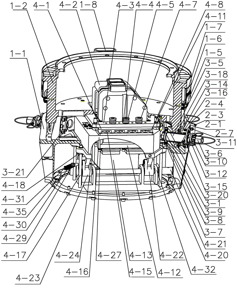
[0023] Specific implementation mode one: combine figure 1 , figure 2 , image 3 , Figure 4 , Figure 5 , Image 6 , Figure 7 and Figure 8 Describe this embodiment. This embodiment includes a tolerance-guided docking device, an electrical connection device, multiple sets of locking and positioning devices, and multiple sets of mechanical connection quick-release devices. The tolerance-guided docking device includes a concave body 1-1 and a convex body 1 -2, the structure of the concave body 1-1 is set in cooperation with the structure of the convex body 1-2, and the concave body 1-1 and the convex body 1-2 are connected by multiple sets of locking and positioning devices and multiple sets of mechanical connection quick release devices Detachable connection, the multiple sets of locking and positioning devices are evenly arranged between the concave body 1-1 and the convex body 1-2, and the multiple sets of mechanical connection quick release devices are evenly distrib...

specific Embodiment approach 2

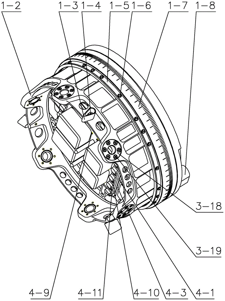
[0030] Specific implementation mode two: combination image 3 and Figure 4 To illustrate this embodiment, the tolerance-guided docking device in this embodiment also includes a guide key 1-3, a connecting screw I1-4, a joint rotation angle indicating angle scale 1-7 and a positioning key 1-8, and the guide key 1 -3 is uniformly installed on the convex body 1-2 through connecting screws I1-4. One end surface of the convex body 1-2 is processed with a first interface connected to the joint, and a positioning key 1-8 is installed on the edge of the first interface to coordinate with the joint. One end face is a second interface connected with the concave body 1-1, and the edge of the second interface is evenly processed with a plurality of lugs along the circumferential direction, and the joint rotation angle indicating angle scale 1-7 is fixedly connected to the convex body 1 -2 on the outer circumferential surface; the outer ring of the concave body 1-1 is uniformly processe...

specific Embodiment approach 3

[0032] Specific implementation mode three: combination figure 1 , figure 2 , image 3 and Figure 5 Describe this embodiment, the mechanical connection quick release device in this embodiment includes a convex body bushing 3-18, a concave body outer ring bushing 3-16, a concave body inner ring bushing 3-20, an open expansion sleeve 3-5 and A plurality of split expansion rings 3-4, the outer ring bushing 3-16 of the concave body is installed on the outer ear plate of the concave body 1-1 through a plurality of connecting screws IV 3-17, and the bushing 3-18 of the convex body passes through A plurality of connecting screws V3-19 are installed on the lugs of the convex body 1-2, and the inner ring bushing 3-20 of the concave body is installed on the inner ear plate of the concave body 1-1 through a plurality of connecting screws VI3-21, The split expansion sleeve 3-5 is arranged on the inner wall of the inner ring bushing 3-20 of the concave body, and a plurality of split ex...


PUM


Abstract

A robot arm joint quick-change interface system allowing on-rail replacement relates to a robot arm joint quick-change interface system. The robot arm joint quick-change interface system solves the problem that an electric connector of a conventional robot arm joint quick-change interface system is damaged due to overload, since the electric connector has no over travel buffering function. A tolerance guiding abutting apparatus comprises a recessed body and a protruding body matching with the recessed body structure, wherein the recessed body and the protruding body are detachably connected through a plurality sets of locking positioners and a plurality sets of mechanical connection and quick-detach apparatuses, the plurality sets of locking positioners are uniformly arranged between the recessed body and the protruding body, and the plurality sets of mechanical connection and quick-detach apparatuses are uniformly arranged between the recessed body and the protruding body. An electrical connecting device is arranged in a cavity formed by the recessed body and the protruding body. The robot arm joint quick-change interface system is used for spatial on-rail maintenance.

Description

technical field [0001] The invention specifically relates to an on-rail replaceable mechanical arm joint quick-change interface system. Background technique [0002] The large-scale space manipulator is the core equipment for space on-orbit maintenance. It has the characteristics of complex structure, high cost, high launch cost, and long on-orbit operation time. At present, the large-scale space manipulators in orbit in the world include the Canadian space station teleoperated manipulator SSRMS and the Japanese experimental module manipulator JEMRMS. Both of these two manipulators are designed to be maintained and replaced on orbit. In order to reduce the maintenance cost of the manipulator, the key to on-orbit maintenance of the manipulator is to replace the failed joint module, so the joint quick-change interface is designed to facilitate rapid replacement and maintenance by astronauts. [0003] The joint quick change interface needs to ensure the rigid connection of the...

Claims


Application Information

Patent Timeline
Patent Type & Authority Applications(China)
IPC IPC(8): B25J17/00
Inventor 史士财何阳王达李荣刘业超刘宏
Owner HARBIN INST OF TECH
Why Eureka
Try Eureka