A quick-change interface system for manipulator joints that can be replaced on rail
A technology of manipulator and interface change, applied in manipulators, joints, manufacturing tools, etc., can solve the problems of lack of over-travel buffer function and overload force damage, to ensure basic performance and integrity, prolong service life, guarantee The effect of a reliable connection
- Summary
- Abstract
- Description
- Claims
- Application Information
AI Technical Summary
Problems solved by technology
Method used
Image
Examples
specific Embodiment approach 1
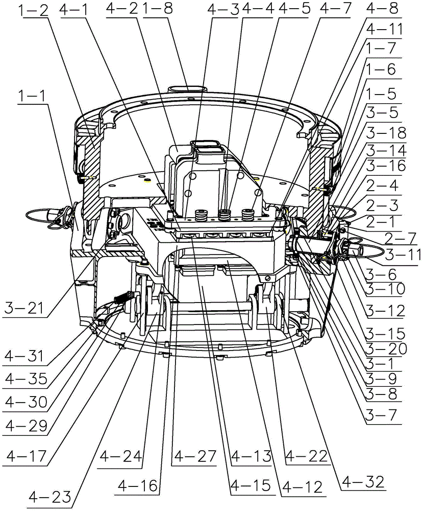
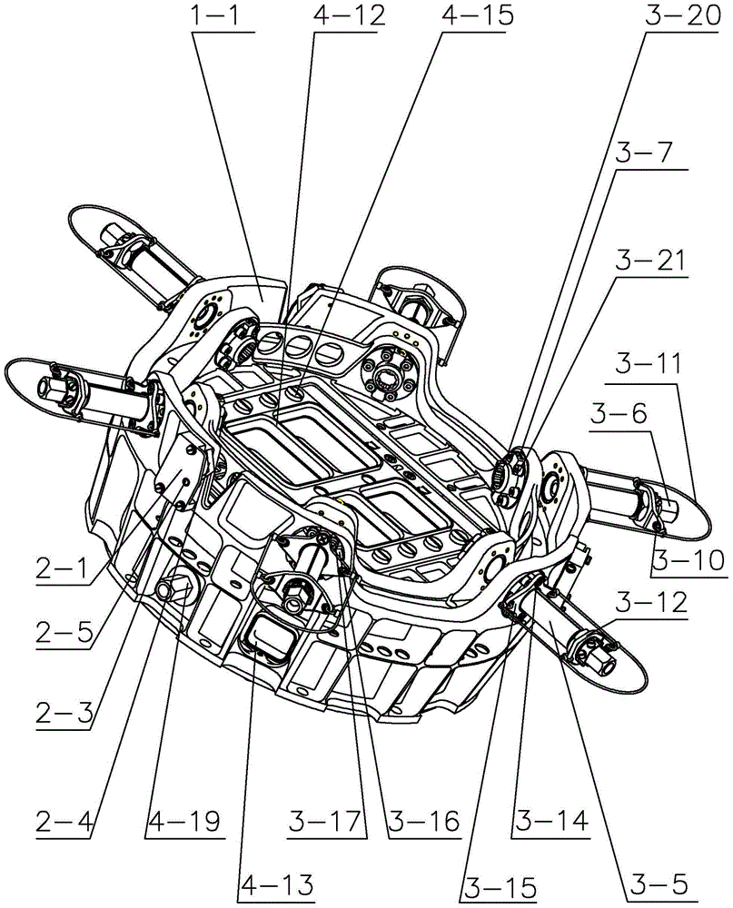
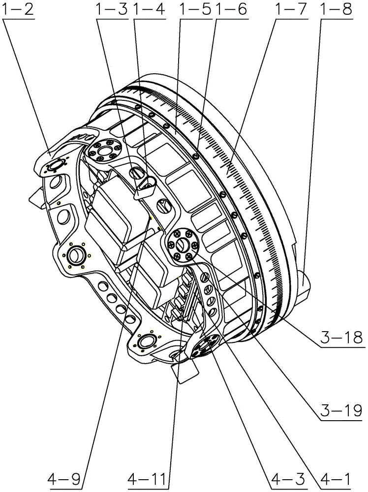
[0023] Specific implementation mode one: combine figure 1 , figure 2 , image 3 , Figure 4 , Figure 5 , Figure 6 , Figure 7 and Figure 8 Describe this embodiment. This embodiment includes a tolerance-guided docking device, an electrical connection device, multiple sets of locking and positioning devices, and multiple sets of mechanical connection quick-release devices. The tolerance-guided docking device includes a concave body 1-1 and a convex body 1 -2, the structure of the concave body 1-1 is set in cooperation with the structure of the convex body 1-2, and the concave body 1-1 and the convex body 1-2 are connected by multiple sets of locking and positioning devices and multiple sets of mechanical connection quick release devices Detachable connection, the multiple sets of locking and positioning devices are evenly arranged between the concave body 1-1 and the convex body 1-2, and the multiple sets of mechanical connection quick release devices are evenly distri...
specific Embodiment approach 2
[0030] Specific implementation mode two: combination image 3 and Figure 4 To illustrate this embodiment, the tolerance-guided docking device in this embodiment also includes a guide key 1-3, a connecting screw I1-4, a joint rotation angle indicating angle scale 1-7 and a positioning key 1-8, and the guide key 1 -3 is uniformly installed on the convex body 1-2 through connecting screws I1-4. One end surface of the convex body 1-2 is processed with a first interface connected to the joint, and a positioning key 1-8 is installed on the edge of the first interface to coordinate with the joint. One end face is a second interface connected with the concave body 1-1, and the edge of the second interface is evenly processed with a plurality of lugs along the circumferential direction, and the joint rotation angle indicating angle scale 1-7 is fixedly connected to the convex body 1 -2 on the outer circumferential surface; the outer ring of the concave body 1-1 is uniformly processe...
specific Embodiment approach 3
[0032] Specific implementation mode three: combination figure 1 , figure 2 , image 3 and Figure 5 Describe this embodiment, the mechanical connection quick release device in this embodiment includes a convex body bushing 3-18, a concave body outer ring bushing 3-16, a concave body inner ring bushing 3-20, an open expansion sleeve 3-5 and A plurality of split expansion rings 3-4, the outer ring bushing 3-16 of the concave body is installed on the outer ear plate of the concave body 1-1 through a plurality of connecting screws IV 3-17, and the bushing 3-18 of the convex body passes through A plurality of connecting screws V3-19 are installed on the lugs of the convex body 1-2, and the inner ring bushing 3-20 of the concave body is installed on the inner ear plate of the concave body 1-1 through a plurality of connecting screws VI3-21, The split expansion sleeve 3-5 is arranged on the inner wall of the inner ring bushing 3-20 of the concave body, and a plurality of split ex...
PUM
 Abstract
Description
Claims
Application Information
 - R&D
- Intellectual Property
- Life Sciences
- Materials
- Tech Scout
- Unparalleled Data Quality
- Higher Quality Content
- 60% Fewer Hallucinations
Browse by: Latest US Patents, China's latest patents, Technical Efficacy Thesaurus, Application Domain, Technology Topic, Popular Technical Reports.
© 2025 PatSnap. All rights reserved.Legal|Privacy policy|Modern Slavery Act Transparency Statement|Sitemap|About US| Contact US: help@patsnap.com


