
A self-priming centrifugal pump

A self-priming centrifugal pump and centrifugal pump technology, applied in the field of centrifugal pumps, can solve the problems of low self-priming efficiency of centrifugal pumps, poor gas-liquid separation effect, slow water feeding speed, etc. The effect of accelerating gas-liquid separation

Inactive Publication Date: 2017-09-26
JIANGSU UNIV
View PDF9 Cites 0 Cited by
  • Summary
  • Abstract
  • Description
  • Claims
  • Application Information

AI Technical Summary

Problems solved by technology

[0005] In view of this, the object of the present invention is to provide a self-priming centrifugal pump: to overcome the defects of low self-priming efficiency, poor gas-liquid separation effect and slow water supply speed in the prior art

Method used


Image

  • A self-priming centrifugal pump
  • A self-priming centrifugal pump
  • A self-priming centrifugal pump

Examples


Embodiment Construction

[0023] The following will clearly and completely describe the technical solutions in the embodiments of the present invention with reference to the drawings in the embodiments of the present invention.

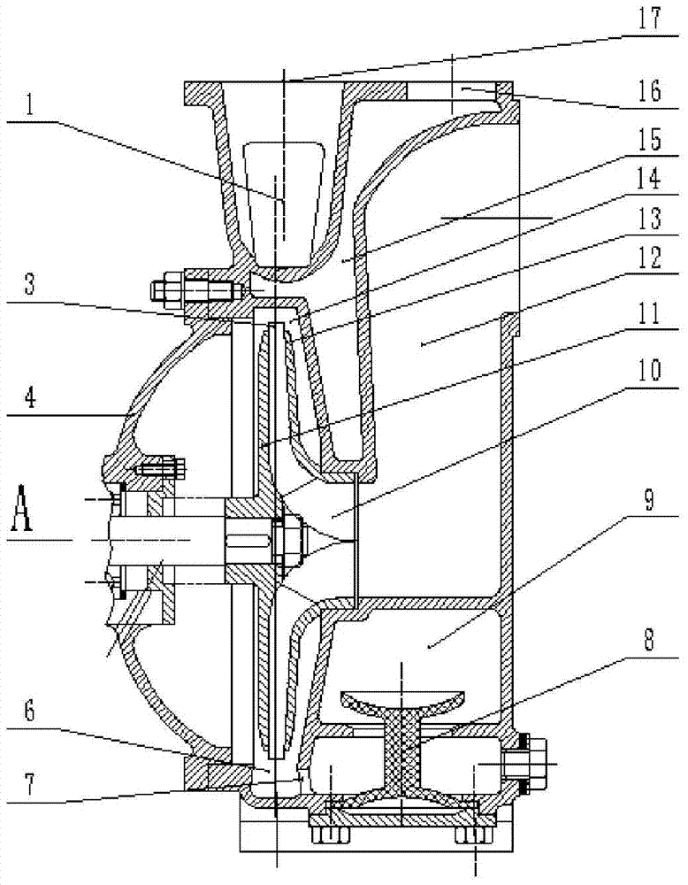
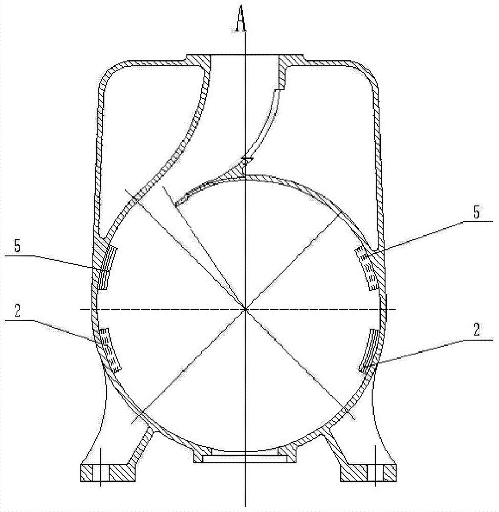
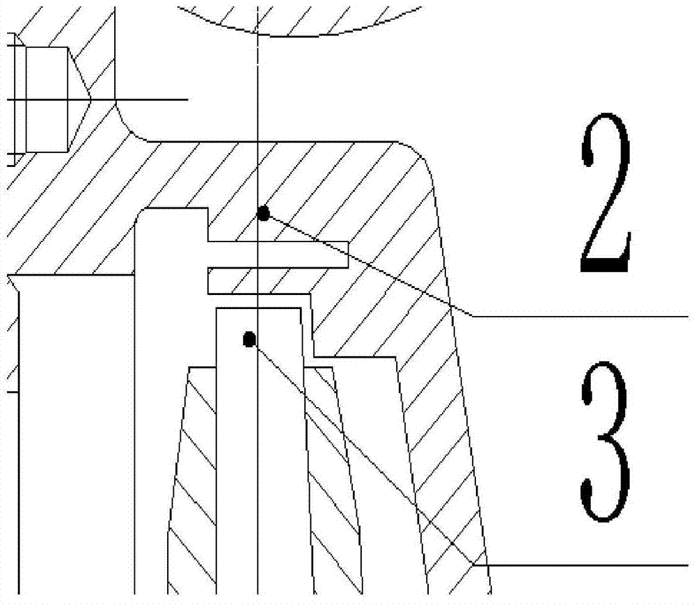
[0024] Reference attached figure 1 , the centrifugal pump includes a pump body and a volute, the volute is located inside the centrifugal pump body, and the volute is provided with a volute water outlet 17, an inlet 1 of the gas-liquid separation chamber, and a return hole 7; the inside of the centrifugal pump body An S-shaped elbow 12 is also provided, and the S-shaped elbow 12 communicates with the impeller inlet 10; the inner cavity of the volute forms the vortex chamber 6 of the self-priming centrifugal pump, and the impeller 3 is also arranged in the vortex chamber 6; The impeller 3 is fixed on the pump shaft through the impeller front cover 13 and the impeller rear cover 11; the volute also includes a front F-shaped sector partition 2 and a rear F-shaped sector partition...


PUM


Abstract

The invention relates to a self-suction centrifugal pump which comprises a pump body, a volute, a front F-shaped sector partition plate and a rear F-shaped sector partition plate. The front F-shaped sector partition plate, the rear F-shaped sector partition plate and the inner wall of the volute are integrally formed, the front F-shaped sector partition plate and the rear F-shaped sector partition plate are staggered, and blades of an impeller project over a front cover plate and a rear cover plate of the impeller by 2-3mm. By the aid of the structure, the blades can sufficiently contact with liquid without large hydraulic loss, disturbance in the pump in starting is enhanced, gas sucked into a pipeline and the pump can be rapidly exhausted, gas-liquid separation is accelerated, gas exhausting time and water feeding time are shortened, and water feeding speed is increased.

Description

technical field [0001] The invention relates to a centrifugal pump, in particular to a pressure water chamber structure with high-efficiency gas-liquid mixing effect applied in a self-priming centrifugal pump. Background technique [0002] The self-priming pump is a special centrifugal pump. It is only necessary to add a certain amount of water to the pump body before starting for the first time. It is not necessary to fill the water inlet pipe with water. . It uses the principle of gas-liquid mixing and the special structure of the pump to realize the suction of gas, and forms a certain degree of vacuum in the suction pipeline of the pump, without the need for other special pumping devices. Just can no longer divert water. It has the advantages of convenient use, reliable work, convenient remote centralized control, and automatic operation, so it is widely used in ships, agriculture, municipal, electric power, mining, chemical industry and other departments, especially su...

Claims


Application Information

Patent Timeline
Patent Type & Authority Patents(China)
IPC IPC(8): F04D9/02
CPCF04D9/02F04D29/426
Inventor 施卫东常浩刘建瑞武永生李小为刘博文
Owner JIANGSU UNIV
Learn More