A Hyperspectral Resolution X-ray Grazing Incidence Microscopic Imaging System
A microscopic imaging and grazing incidence technology, which is applied in the fields of X-ray optics and ion plasma diagnosis, can solve the problems of poor energy resolution of multi-layer films, achieve the effect of small solid angle of receiving light, reduce aberration, and improve spatial resolution
- Summary
- Abstract
- Description
- Claims
- Application Information
AI Technical Summary
Problems solved by technology
Method used
Image
Examples
Embodiment 1
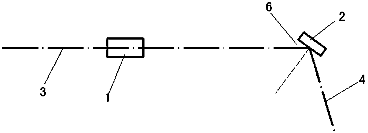
[0030] figure 1 , figure 2 It is a schematic diagram of the optical path of Embodiment 1 of the present invention. The first optical device 1 adopts a multilayer film reflector, and the second optical device 2 adopts a curved crystal. The optical axes of the multilayer film reflector and the curved crystal are perpendicular to each other. The X-ray passes through the multi-layer film mirror and is focused in the meridional direction to form a quasi-monochromatic one-dimensional image, and then through the curved crystal to achieve focus in the sagittal direction, and through the curved crystal to split light to form a highly monochromatic two-dimensional image , and finally imaged onto the recording medium. The main parameters of the system are selected according to the requirements of conventional ICF diagnosis. The specific parameters are as follows: working energy point 2.5keV, object distance 142.5mm, distance between mirror and curved crystal 20mm, image distance 2850mm...
Embodiment 2
[0033] Figure 14 , Figure 15 It is a schematic diagram of the optical path of Embodiment 2 of the present invention. Both the first optical device 1 and the second optical device 2 of this embodiment use spherical curved crystals, and the Si (111) crystal plane is selected as the curved crystal reflection surface. According to the Bragg principle, the crystal The surface is 14.308° at 8keV grazing incidence angle (ie Bragg angle). See Table 1 and Table 2 for detailed parameters and optical component parameters.
[0034] Table 1
[0035] object distance
spacing
image distance
energy point
Collecting solid angle
200mm
20mm
4000mm
8keV
20
1×10 -6 sr
[0036] Table 2
[0037]
[0038] Figure 14 , Figure 15 As shown in , 3 is the incident light, 4 is the outgoing light and 5 is the Bragg angle.
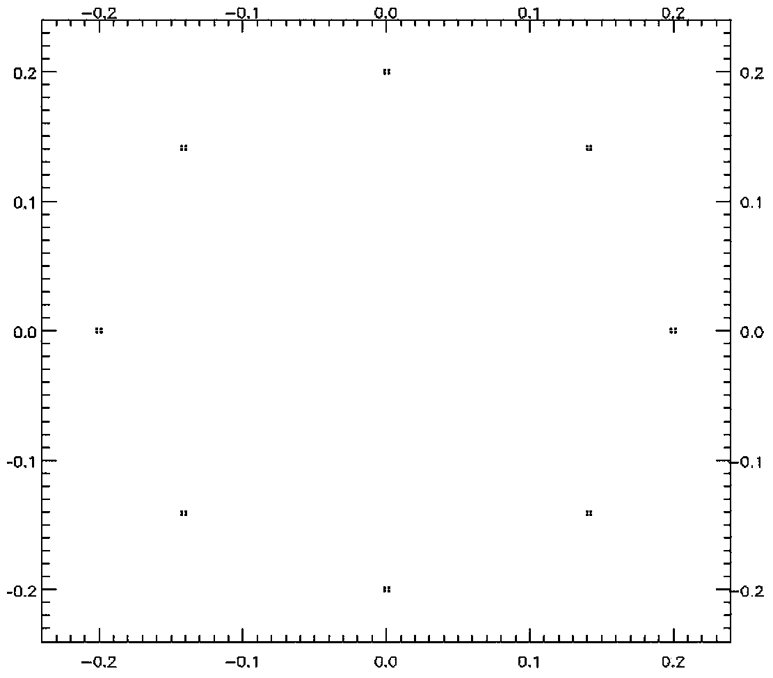
[0039] The scheme proposed in Example 2 is simulated by using the X-ray simulation software SHADOW. Light sou...
PUM
| Property | Measurement | Unit |
|---|---|---|
| reflectance | aaaaa | aaaaa |
Abstract
Description
Claims
Application Information
 - R&D
- Intellectual Property
- Life Sciences
- Materials
- Tech Scout
- Unparalleled Data Quality
- Higher Quality Content
- 60% Fewer Hallucinations
Browse by: Latest US Patents, China's latest patents, Technical Efficacy Thesaurus, Application Domain, Technology Topic, Popular Technical Reports.
© 2025 PatSnap. All rights reserved.Legal|Privacy policy|Modern Slavery Act Transparency Statement|Sitemap|About US| Contact US: help@patsnap.com


