Method for positioning low-frequency oscillation disturbance source of electric power system

A disturbance source location, low frequency oscillation technology, applied in the fault location and other directions, can solve problems such as the location method of the disturbance source of the low frequency oscillation that is not seen, and achieve the effect of avoiding further expansion and avoiding failures

Inactive Publication Date: 2015-08-05
SOUTH CHINA UNIV OF TECH
View PDF5 Cites 16 Cited by
  • Summary
  • Abstract
  • Description
  • Claims
  • Application Information

AI Technical Summary

Problems solved by technology

However, there is no public low-frequency oscillation disturbance source location method

Method used


Image

  • Method for positioning low-frequency oscillation disturbance source of electric power system
  • Method for positioning low-frequency oscillation disturbance source of electric power system
  • Method for positioning low-frequency oscillation disturbance source of electric power system

Examples


Embodiment 1

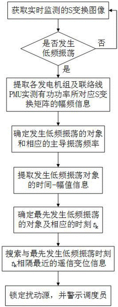
[0039] like figure 1 As shown, the specific conditions of the power system low-frequency oscillation disturbance source location method described in this embodiment are as follows:

[0040] 1) With the help of the data recording function of the WAMS system, the real-time monitored active power signal and its S-transformed image are obtained, and the S-transformed image is used to judge whether the power grid has low-frequency oscillation, as follows:

[0041] The S-transform of active power signal x(t) is defined as:

[0042] S ( τ , f ) = ∫ - ∞ ∞ x ( t ) ( | f | 2 π e ...

Embodiment 2

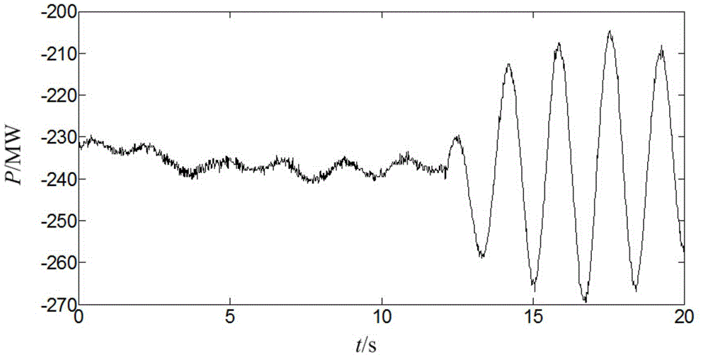
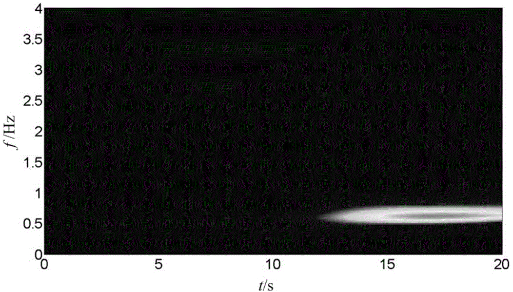
[0070] The difference from Embodiment 1 is that this embodiment takes the active power data monitored by the PMU of a domestic provincial power grid on May 8, 2013 as an example, such as Figure 6 shown. Figure 7 is the S-transform image corresponding to the data. from Figure 6 It can be intuitively judged that low-frequency oscillation has occurred in the power grid, and there are currently three oscillation modes.

[0071] Extract the amplitude-frequency information of the S matrix, such as Figure 8 shown. The threshold δ is set to 2. It can be seen that there is a dominant oscillation mode with a frequency of 0.20 Hz at the current moment.

[0072] Extract the time and amplitude information corresponding to the dominant oscillation frequency, and perform differential processing, the result is as follows Figure 9 shown. From this, the starting time t of the low frequency oscillation can be determined k = 11.2s.

[0073] Finally, the disturbance source is locked ...


PUM


Abstract

The invention discloses a method for positioning a low-frequency oscillation disturbance source of an electric power system, which comprises the following steps: 1) determining whether a low-frequency oscillation occurs in a power grid according to an S transformation image; 2) extracting amplitude frequency information in an S transformation matrix which corresponds with an active power signal that is actually measured by each power generator set and each tie line phasor measurement unit (PMU), determining an object with the low-frequency oscillation and a corresponding dominant oscillation frequency; 3) extracting time and amplitude information which correspond with the dominant oscillation frequency in each S matrix, determining the object in which the low-frequency oscillation firstly occurs and a corresponding time point tk; and 4) determining the disturbance source of the low-frequency oscillation based on a disturbance time correlation analyzing method. The method of the invention has functions of quickly locking the disturbance source, helping a dispatcher to quickly and accurately analyze the reason of oscillation, taking effective control measures in time for quickly stopping oscillation, and preventing further enlargement of the fault.

Description

technical field [0001] The invention relates to the technical field of locating a low-frequency oscillation disturbance source of a power system, in particular to a method for locating a low-frequency oscillation disturbance source of a power system. Background technique [0002] The problem of low-frequency oscillation of power system belongs to the category of dynamic stability of power system. It was first proposed in the late 1960s. After about half a century of development, relevant scholars at home and abroad have studied the mechanism of low-frequency oscillation, analysis and identification methods, control methods and measures. Extensive research has been carried out, and great progress has been made in the understanding of low-frequency oscillation problems in power systems. At the same time, due to the complexity of the problem, low-frequency oscillation events still occur from time to time in my country's actual power grid. Power system low-frequency oscillation...

Claims


Application Information

Patent Timeline
Patent Type & Authority Applications(China)
IPC IPC(8): G01R31/08
Inventor 温伯坚席禹蔡泽祥刘明波
Owner SOUTH CHINA UNIV OF TECH
Why Eureka
Try Eureka