
Wide-angle lens

A wide-angle lens, negative lens technology, applied in the field of wide-angle lens, can solve problems such as initial investment increase

Inactive Publication Date: 2015-08-05
HOYA CORP
View PDF9 Cites 19 Cited by
  • Summary
  • Abstract
  • Description
  • Claims
  • Application Information

AI Technical Summary

Problems solved by technology

However, if the lens for a surveillance camera corresponding to a megapixel is designed as an aspheric glass lens, the initial investment will increase if the production volume is small.

Method used


Image

  • Wide-angle lens
  • Wide-angle lens
  • Wide-angle lens

Examples


Embodiment 1

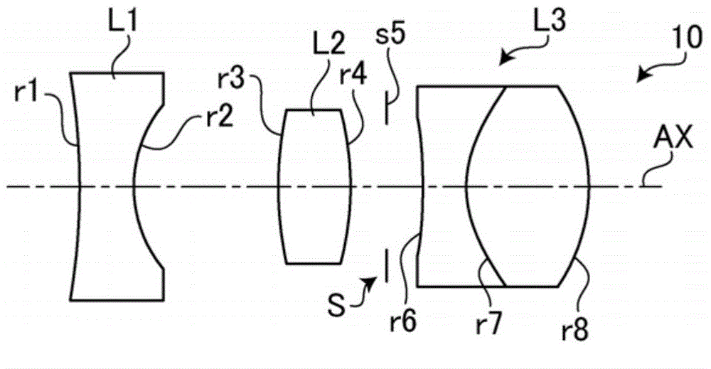
[0144] As described above, the structure of the wide-angle lens 10 of Embodiment 1 of the present invention is as follows figure 1 shown. In the present Example 1, the negative lens group is composed of a negative lens L1 made of glass. The cemented lens L3 has a structure in which a negative lens and a positive lens are arranged from the object side.

[0145] Table 1 shows specific numerical values ​​(surface data, aspheric surface data, and various data) of the wide-angle lens 10 of the first embodiment. The numbers NO and figure 1 The surface symbol rn (n is a natural number) and the aperture symbol sn correspond to each other. "*" added to the number NO in Table 1 (surface data) indicates that the surface corresponding to the number NO is an aspherical surface. In Table 1 (surface data), R (unit: mm) indicates the radius of curvature of each surface of the optical component, D (unit: mm) indicates the thickness of the optical component or the distance between optical c...

Embodiment 2

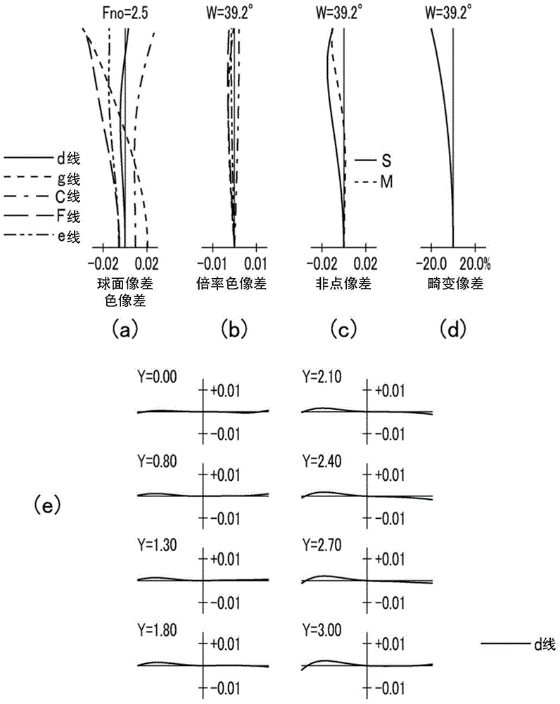
[0152] image 3 It is a layout diagram showing the structure of the wide-angle lens 10 according to the second embodiment of the present invention. In Example 2, the negative lens group is composed of a negative lens L1 made of resin. The cemented lens L3 has a structure in which a positive lens and a negative lens are arranged from the object side. Figure 4 (a) to (e) are diagrams of various aberrations (spherical aberration, axial chromatic aberration, lateral chromatic aberration, astigmatism, distortion aberration, lateral aberration) of the wide-angle lens 10 of the second embodiment . Table 2 shows the specific numerical configuration (surface data, aspheric surface data, various data) of the wide-angle lens 10 of the second embodiment.

[0153] 【Table 2】

[0154] Example 2

[0155]

Embodiment 3

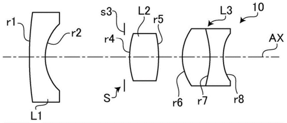
[0157] Figure 5 It is a lens arrangement diagram showing the structure of the wide-angle lens 10 according to the third embodiment of the present invention. In the third embodiment, the negative lens group is composed of a negative lens L1 made of resin. The cemented lens L3 has a structure in which a positive lens and a negative lens are arranged from the object side. Figure 6 (a) to (e) are diagrams of various aberrations (spherical aberration, axial chromatic aberration, lateral chromatic aberration, astigmatism, distortion aberration, lateral aberration) of the wide-angle lens 10 of the third embodiment . Table 3 shows the specific numerical configuration (surface data, aspheric surface data, various data) of the wide-angle lens 10 of the third embodiment.

[0158] 【table 3】

[0159] Example 3

[0160]


PUM


Abstract

The invention provides a wide-angle lens. Manufacturing simplicity is ensured and improvement of optical properties is achieved through a low component number. The wide-angle lens comprises a negative lens group with one or two positive lenses, a positive glass lens and a positive connection lens formed by a positive resin lens and a negative resin lens through connection from an object side in order. The wide-angle lens is a wide-angle lens with a half field angle of more than 30 degrees. The connection surface of the connection lens is designed to be an aspheric surface with a decreasing sagging amount from the optical axis to the rim when the surface is compared with a paraxial spherical surface defined by paraxial curvature radius of the connection surface.

Description

technical field [0001] The present invention relates to a wide-angle lens mounted on a surveillance camera or the like. Background technique [0002] Lenses for surveillance cameras can electronically correct captured images. Therefore, they are usually designed with a small number of lens components, and their wide-angle and low cost are prioritized over optical distortion correction. In addition, lenses for surveillance cameras use bright pan-focus lenses with an F-stop of less than 2, for example, to compensate for insufficient sensitivity of the sensor, or use glass lenses to ensure durability for outdoor use or to suppress changes in the focus position due to temperature changes. lens. [0003] Surveillance cameras have become capable of handling high-resolution image data due to the development of digitalization with the spread of digital communication facilities such as networks and LANs (Local Area Networks). Therefore, in order to obtain magnification of the surve...

Claims


Application Information

Patent Timeline
Patent Type & Authority Applications(China)
IPC IPC(8): G02B13/18G02B13/06
CPCG02B13/002G02B13/06
Inventor 丸山晃一
Owner HOYA CORP
Learn More