Noise optimization method for engine intake system

A technology of air intake system and optimization method, which is applied in special data processing applications, instruments, electrical digital data processing, etc., can solve the problems of low cost, high cost, and low efficiency, and achieve low cost, high optimization efficiency, and solution less efficient effect

Inactive Publication Date: 2015-08-05
CHENGDU LINGCHUAN SPECIAL IND
View PDF3 Cites 3 Cited by
  • Summary
  • Abstract
  • Description
  • Claims
  • Application Information

AI Technical Summary

Problems solved by technology

[0006] The invention provides a noise optimization method for the engine intake system, which solves the technical problems of low efficiency and high cost in the existing noise optimization meth

Method used


Image

  • Noise optimization method for engine intake system

Examples


Embodiment 1

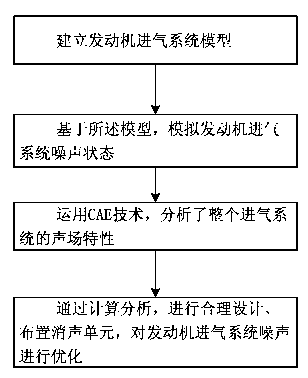
[0024] In Embodiment 1, a noise optimization method for the engine air intake system is provided, please refer to figure 1 , the method includes:

[0025] Step 1: Establish a model of the engine intake system;

[0026] Step 2: Based on the model, simulate the noise state of the engine intake system;

[0027] Step 3: Use CAE technology to analyze the sound field characteristics of the entire intake system;

[0028] Step 4: Through calculation and analysis, rationally design and arrange the muffler unit, and optimize the noise of the engine intake system.

[0029] Wherein, in the embodiment of the present application, the intake system noise is specifically divided into: air noise and structure noise.

[0030] Among them, in the embodiment of the present application, the air intake system of the engine is a very complex noise source, including various types of noises, and the mechanism of each noise is different. Therefore, to optimize the noise of the intake system, it is f...


PUM


Abstract

The invention discloses a noise optimization method for an engine intake system. The method comprising the following steps: step one, establishing an engine intake system model; step two, simulating the noise state of the engine intake system based on the model; step three, analyzing acoustic field characteristics of the entire intake system by using CAE technology; and step four, optimizing the noise of the engine intake system by calculating, analyzing, reasonably designing and arranging of a noise elimination unit. By virtue of the noise optimization method for the engine intake system, the technical effects of reasonable design, high optimization efficiency and low cost are implemented.

Description

[0001] technical field [0002] The invention relates to the research field of an engine intake system, in particular to a noise optimization method for an engine intake system. Background technique [0003] Now NVH (noise, vibration and comfort) performance has become an important indicator to evaluate the quality of automobiles; major OEMs are committed to improving their brand value and market competitiveness by improving the NVH performance of automobiles; at the same time, as people With the continuous attention to noise pollution, the regulations on automobile noise are becoming more and more stringent; intake noise, as an important noise source of automobiles, has also received sufficient attention; and traditional design methods can no longer respond quickly to market demand and design products that meet the needs of the market. Intake system required. [0004] To sum up, in the process of realizing the technical solution of the invention in the embodiment of the pr...

Claims


Application Information

Patent Timeline
IPC IPC(8): G06F17/50
Inventor 汪庭文黄柳志杨军
Owner CHENGDU LINGCHUAN SPECIAL IND
Why Eureka
Try Eureka