
Surface cleaning device for solar cell module

A surface cleaning device, a technology for solar cells, applied in cleaning methods and utensils, cleaning methods using tools, chemical instruments and methods, etc., can solve the problems of power consumption, large movement resistance, poor cleaning effect, etc. Snow or foreign matter, low running cost, good cleaning effect

Inactive Publication Date: 2015-08-12
白峻光 +3
View PDF7 Cites 13 Cited by
  • Summary
  • Abstract
  • Description
  • Claims
  • Application Information

AI Technical Summary

Problems solved by technology

[0002] The surface of the battery module for solar power generation is often covered with a layer of dust. Floating dust can lead to a significant drop in the power generation efficiency of the solar battery module. The disadvantage is that the cleaning method belongs to the scraping method. When working, force is applied in one direction, there is no inertia, and the movement resistance is large. It needs to be equipped with a high-power motor, which consumes more power. The bristles on one side are limited by the movement method, and the cleaning is not thorough, especially in snowfall. Sometimes, the straight dust brush has poor cleaning effect on the snow and there are residues; there is another method of cleaning the solar cell module array by a large-scale cleaning vehicle, but it is necessary to reserve a place next to the solar cell module array to accommodate the passage of the cleaning vehicle. The cleaning of roads reduces the utilization rate of land, and the daily use, maintenance and maintenance of sweeping vehicles will incur costs, resulting in high operating costs for cleaning work

Method used


Image

  • Surface cleaning device for solar cell module
  • Surface cleaning device for solar cell module
  • Surface cleaning device for solar cell module

Examples


Embodiment Construction

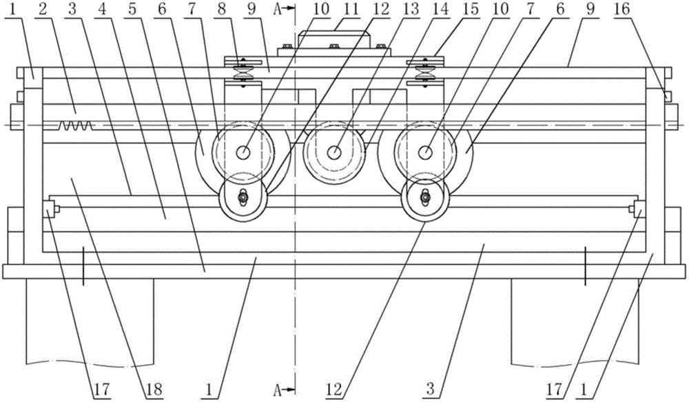
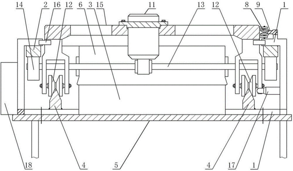
[0012] The solar cell module surface cleaning device has a frame 1, a support rail 9, a rack 2, a gantry track 4, a gantry frame 15, a motor 11 and several roller brushes 6, and the frame is fixed on the solar cell module 3 by a bolt assembly On the mounting frame 5 of the gantry frame, wherein the support rail, the rack and the gantry track are fixedly connected with the frame respectively, and the support rail, the rack and the gantry track are arranged in parallel, and the feet of the gantry frame are movably connected with the gantry track through the walking wheels 12, so that The two feet of the gantry frame are located on both sides of the solar cell module. The side of the gantry frame is equipped with support wheels 8, which are flexibly connected to the support rails. The support wheels and walking wheels are pulleys. The rails of the gantry track The surface is a trapezoidal surface that matches the pulley. The trapezoidal surface can reduce the accumulation of snow ...


PUM


Abstract

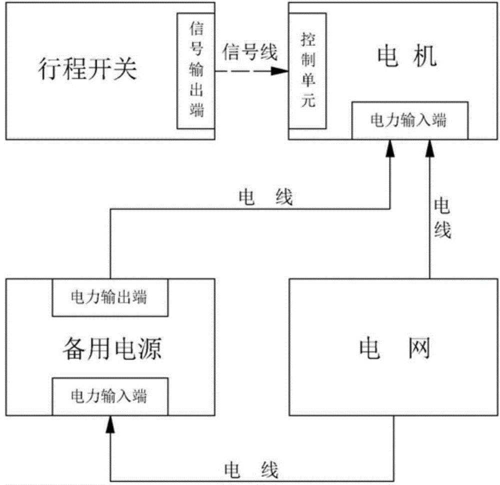
The invention discloses a surface cleaning device for a solar cell module. The surface cleaning device comprises a frame, a strut rail, racks, a gantry rail, a portal frame, a motor and a plurality of brush wheels, wherein the strut rail, the racks and the gantry rail are respectively fixedly connected to the frame; the feet ends of the portal frame are movably connected to the gantry rail through travelling wheels; supporting wheels are arranged on the lateral surface of the portal frame; the supporting wheels and the strut rail are in movable pressure welding; the supporting wheels and the travelling wheels are pulleys; the plurality of brush wheels are rotatably connected to a shaft hole of the portal frame through brush shafts; each brush shaft is fixedly connected to a brush gear; a shell of the motor is fixedly connected to the portal frame; an output shaft of the motor is fixedly connected to a motor gear; the motor gear and each brush gear are respectively engaged with the corresponding rack; teeth of each rack are arranged at the bottom surface of each rack; a reserve power supply is arranged on the frame; travel switches are arranged on the frame or the portal frame; the motor is provided with a control unit; signal output ends of the travel switches are communicated with a motor control unit signal through a signal line.

Description

technical field [0001] The invention provides a device for cleaning the surface of a solar battery module, which belongs to the field of accessories for solar power generation panels. Background technique [0002] The surface of the battery module for solar power generation is often covered with a layer of dust. Floating dust can lead to a significant drop in the power generation efficiency of the solar battery module. The disadvantage is that the cleaning method belongs to the scraping method. When working, force is applied in one direction, there is no inertia, and the movement resistance is large. It needs to be equipped with a high-power motor, which consumes more power. The bristles on one side are limited by the movement method, and the cleaning is not thorough, especially in snowfall. Sometimes, the straight dust brush has poor cleaning effect on the snow and there are residues; there is another method of cleaning the solar cell module array by a large-scale cleaning ...

Claims


Application Information

Patent Timeline
Patent Type & Authority Applications(China)
IPC IPC(8): B08B1/04
CPCB08B1/32
Inventor 白峻光白岩松白凇会刘艳萍
Owner 白峻光
Learn More