Supercharge Your Innovation With Domain-Expert AI Agents!

Thin-wall pipe chipless cutting device and thin-wall pipe chipless cutter

A cutting device and thin-walled pipe technology, applied in the direction of feeding device, positioning device, storage device, etc., can solve the problems of non-circumferential shrinkage of the pipe mouth, adduction of the incision, high manufacturing cost, etc., and achieve no deformation and burr in the incision, The overall structure is simple and the cut is smooth

Active Publication Date: 2015-08-12
JIANGSU UNIV OF SCI & TECH +1
View PDF8 Cites 2 Cited by
  • Summary
  • Abstract
  • Description
  • Claims
  • Application Information

AI Technical Summary

Problems solved by technology

However, the pipe fittings cut by the three hobs in the hob cutting device have a retraction phenomenon, and the pipe ends still need to be corrected before they can be used in the next process; The obtained pipe fittings are deformed in the punching direction, and the nozzle is not circumferentially contracted, and the pipe end needs to be corrected before it can be used in the next process
[0004] The cutting device of the latest chipless cutting machine is as described in the patent ZL200910144550.X chipless cutting device for thin-walled pipes. The cutting of thin-walled pipes is realized by moving the movable mandrel following the moving cutting die, and the movable mandrel is completed. Return to the original position after cutting to facilitate the next set of pipes to be cut. This device can realize chipless cutting of pipes, but the structure of the mandrel assembly is complex and the manufacturing cost is high

Method used


Image

  • Thin-wall pipe chipless cutting device and thin-wall pipe chipless cutter
  • Thin-wall pipe chipless cutting device and thin-wall pipe chipless cutter
  • Thin-wall pipe chipless cutting device and thin-wall pipe chipless cutter

Examples


Embodiment Construction

[0021] Specific embodiments of the present invention will be described in detail below in conjunction with the accompanying drawings.

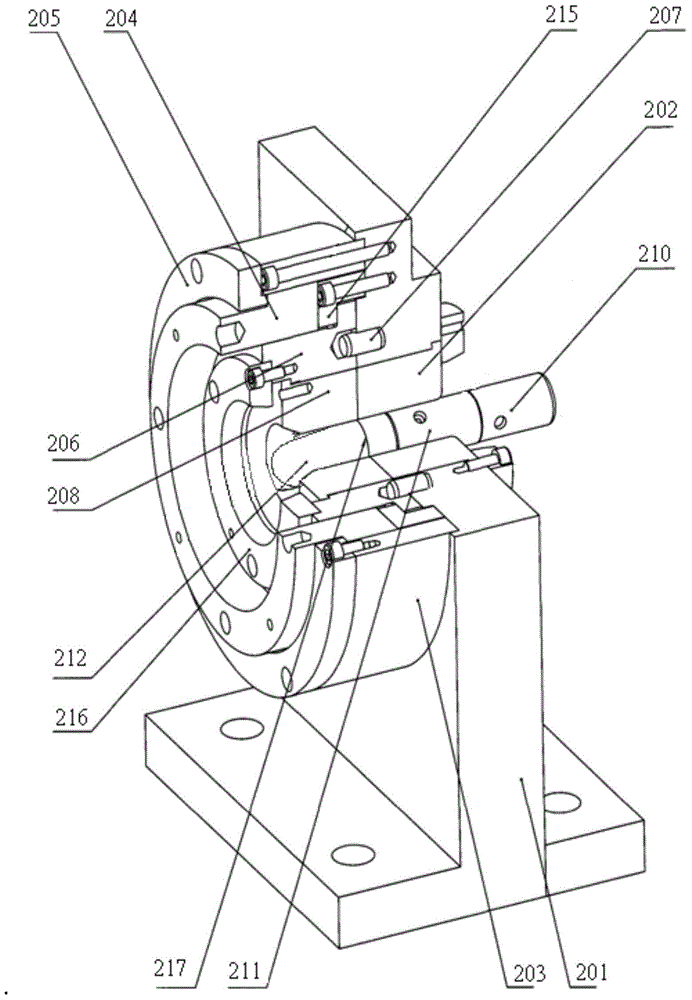
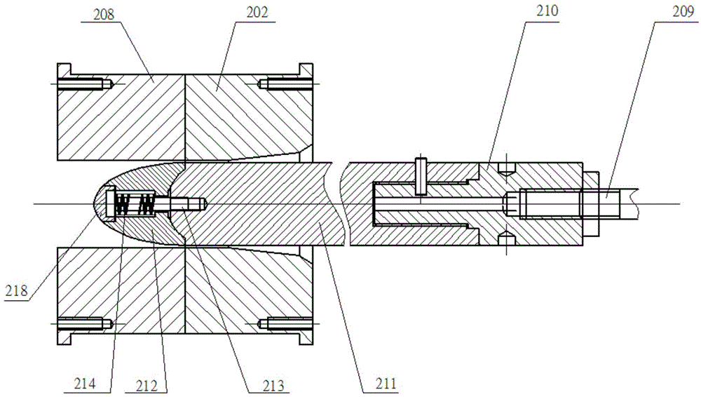
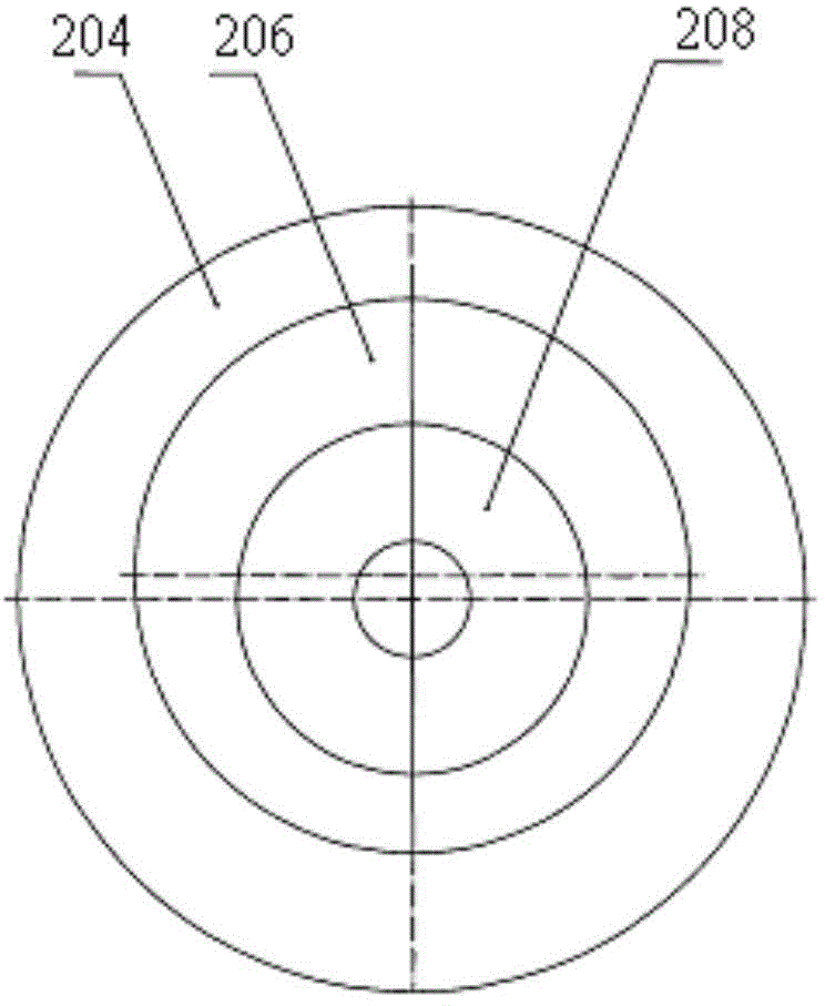
[0022] Such as figure 1 , 2 As shown, the chip-free cutting device for thin-walled pipes includes: a fixed seat 201, a fixed cutting die 202 is arranged in the fixed seat 201, a rotary jacket 203 is arranged on one side of the fixed seat 201, and the rotary jacket 203 moves through the first pressure ring 205. A rotary sleeve 204 with internal and external eccentricity is provided, and the first pressing ring 205 is fixed on the rotary outer sleeve 203 through fixing bolts. In the rotary sleeve 204, an outer mold base 206 with internal and external eccentricity is installed through the second pressing ring 215. The second pressing ring 215 Fixed on the fixed seat 201 by fixing bolts, the eccentricity of the rotary sleeve 204 and the outer mold base 206 is equal, and its value must be greater than the sum of the pipe wall thickness and the gap...


PUM


Abstract

The invention discloses a thin-wall pipe chipless cutting device comprising a fixed base, a fixed cutting mode, a rotary jacket, a rotary sleeve, and a fixed sleeve. A movable cutting mode matched with the fixed cutting mode is arranged in an outer mold base. A core rod assembly is arranged in the fixed and movable cutting modes in a penetrating way. The core rod assembly comprises a positioning piece. A connecting base, a fixed core rod and a movable core rod are sequentially arranged on the positioning piece. The movable core rod is provided with an installation through hole inside. A guide bolt is installed in the installation through hole in a penetrating way. The cap of the guide bolt presses against the end face of the movable core rod. The end of the guide bolt is arranged in a penetrating way in a threaded hole arranged in the end of the fixed core rod. The guide bolt is sleeved with a pressure spring in the position corresponding to a pressure spring installation section. The thin-wall pipe chipless cutting device of the invention is simple in structure, low in manufacture cost, and convenient to install. The invention further discloses a thin-wall pipe chipless cutter based on the thin-wall pipe chipless cutting device.

Description

technical field [0001] The invention relates to a pipe cutting device, in particular to a chipless cutting device for thin-walled pipes and a chipless cutting machine for thin-walled pipes based on the cutting device. Background technique [0002] Thin-walled pipes after bending are widely used in industrial production. The pipes need to be cut before bending. The traditional cutting machine adopts the sawing method, which will not only generate a lot of chips, but also deform the pipes, which need to be corrected before For subsequent processing. This makes the production cost of thin-walled pipe products higher and the production efficiency is low. [0003] At present, the newer cutting technology is chipless cutting technology. The chipless cutting devices for thin-walled pipes mainly include hob cutting devices and punching devices. Compared with traditional saw blade cutting devices, they have high processing accuracy and no debris generation. advantage. However, the...

Claims


Application Information

Patent Timeline
IPC IPC(8): B21D28/02B21D28/14B21D43/02
CPCB21D28/02B21D28/14B21D43/02
Inventor 唐文献张建朱慧林洪才李钦奉朱永梅苏世杰晏飞
Owner JIANGSU UNIV OF SCI & TECH
Features
  • R&D
  • Intellectual Property
  • Life Sciences
  • Materials
  • Tech Scout
  • Unparalleled Data Quality
  • Higher Quality Content
  • 60% Fewer Hallucinations
Learn More