Supercharge Your Innovation With Domain-Expert AI Agents!

Punch built-in multi-station displacement die manipulator

A built-in, manipulator technology, applied in the direction of manipulators, program-controlled manipulators, feeding devices, etc., can solve the problems of dangerous operation, high labor intensity, long standby time of punch presses, etc., and achieve the effect of stable and reliable action and concise overall structure

Active Publication Date: 2016-08-24
SOHBI CRAFT CHANGSHU
View PDF7 Cites 0 Cited by
  • Summary
  • Abstract
  • Description
  • Claims
  • Application Information

AI Technical Summary

Problems solved by technology

Most of the existing technologies still use the original manual operation method to move the mold artificially by the online workers. One of the self-evident shortcomings of this operation method is that due to the slow speed of the mold movement, the punching machine has a long standby time, which affects the molding of the workpiece. efficiency; second, due to the high labor intensity of online operators and always in a high state of tension, they are prone to fear and even refuse to engage in this work; third, due to the low safety factor, there is a risk of operational danger
[0003] Utilizing the mold-moving manipulator to move the mold can undoubtedly eliminate the aforementioned shortcomings, but after searching by the applicant, no matter whether it is in the Chinese and foreign patent documents or in the non-patent literature, there is no evidence that the structure is reasonable, the action is stable and reliable, the applicability is strong, and it can be used with The technical information of the multi-station (that is, multi-process, the same below) punching machine in the prior art that is compatible with the machine

Method used


Image

  • Punch built-in multi-station displacement die manipulator
  • Punch built-in multi-station displacement die manipulator
  • Punch built-in multi-station displacement die manipulator

Examples


Embodiment Construction

[0019]In order to enable the examiners of the patent office, especially the public, to understand the technical essence and beneficial effects of the present invention more clearly, the applicant will describe in detail the following in the form of examples, but none of the descriptions to the examples is an explanation of the solutions of the present invention. Any equivalent transformation made according to the concept of the present invention which is merely formal but not substantive shall be regarded as the scope of the technical solution of the present invention.

[0020] In the following descriptions, all concepts involving up, down, left, right, front and rear directionality (or orientation) are for the position state of the picture being described, and the purpose is to facilitate the public Therefore, it cannot be understood as a special limitation on the technical solution provided by the present invention.

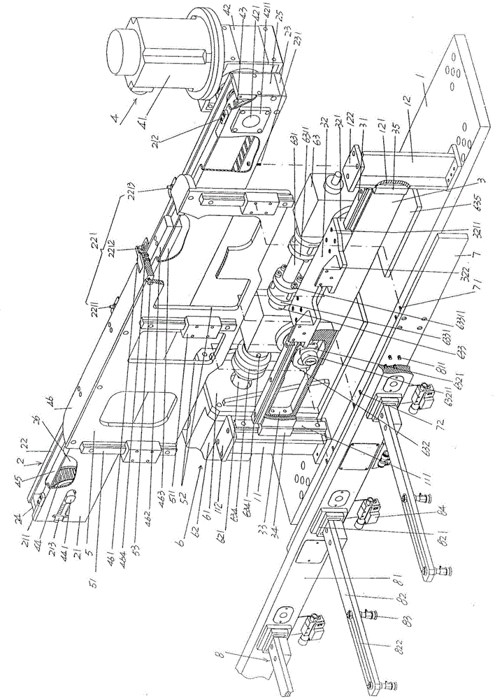
[0021] See figure 1 , a punch work platform fixed seat 1...


PUM


Abstract

The invention discloses a punching machine built-in type multi-station mode moving manipulator, and belongs to the technical field of automatic machinery. The punching machine built-in type multi-station mode moving manipulator comprises a punching machine working platform fixed base, a support cross beam, a lifting cross beam, a slide frame driving mechanism, a slide frame, a lifting cross beam driving mechanism, and a mechanical arm connecting plate, wherein fixed base left and right stand columns are arranged on the punching machine working platform fixed base; fixed base left and right stand column guide rails are arranged on the fixed base left and right stand columns; the left and right ends of the support cross beam are respectively fixed with the fixed base left and right stand columns; the left and right ends of the lifting cross beam are respectively in slide fit with the fixed base left and right stand column guide rails, and a connecting plate translation guide rail is arranged at the top of the lifting cross beam; a connecting plate fixed base is arranged on the connecting plate translation guide rail; the slide frame driving mechanism is arranged on the support cross beam; the slide frame is provided with at least one pair of mechanical arm connecting plate lifting guide rails; the lifting cross beam driving mechanism is arranged on the punching machine working platform fixed base; the mechanical arm connecting plate is fixed with the connecting plate fixed base; and one set of workpiece automatic extraction and release mechanisms is fixed at the forward side of the mechanical arm connecting plate. The punching machine built-in type multi-station mode moving manipulator is simple in whole structure, stable and reliable in actions, excellent in automatic effect, and convenient to be carried on a punching machine working platform.

Description

technical field [0001] The invention belongs to the technical field of automatic machinery, and in particular relates to a built-in punch press multi-station displacement die manipulator. Background technique [0002] The stamping and forming of the same workpiece by the same punch press according to the process requirements has at least the following advantages: first, it can significantly reduce the number of punch presses used, save equipment investment, and maximize the use of resources; second, save Occupation of space; the third is to save mold costs; the fourth is to facilitate the maintenance and maintenance of equipment; the fifth is high stamping efficiency and can save valuable human resources, etc. However, the problem of mold shifting for workpieces has long plagued the industry. The so-called mold shifting refers to transferring the workpiece from the mold (lower mold) of the previous or previous station to the mold (lower mold) of the next station. . Most of...

Claims


Application Information

Patent Timeline
Patent Type & Authority Patents(China)
IPC IPC(8): B21D43/04B25J9/08
CPCB21D43/04B25J9/08
Inventor 高健顾建军周赟
Owner SOHBI CRAFT CHANGSHU
Features
  • R&D
  • Intellectual Property
  • Life Sciences
  • Materials
  • Tech Scout
  • Unparalleled Data Quality
  • Higher Quality Content
  • 60% Fewer Hallucinations
Learn More