
Safety drill chuck

A drill chuck, a safe technology, applied in drilling tool accessories, tool joints, drilling/drilling equipment, etc., can solve the problem that the nut sleeve and the nut are prone to relative sliding, cannot effectively adjust the jaws, and the drill bit falls off and fly out. and other problems to achieve the effect of preventing slippage, uniform and stable torque transmission, and ensuring efficiency

Active Publication Date: 2015-08-12
ZHEJIANG CHAOLI MECHANICAL TOOLS
View PDF9 Cites 3 Cited by
  • Summary
  • Abstract
  • Description
  • Claims
  • Application Information

AI Technical Summary

Problems solved by technology

The three jaws are respectively installed in the three slideways of the drill body. By rotating the drill chuck, the external threads on the jaws match the internal threads on the drill chuck to realize the oblique movement of the jaws, and the precise automatic positioning. Usually a drill chuck can be equipped with different drilling tools (such as center drill, drill bit, reamer, tap, etc.). In the prior art, in order to ensure that the drilling tools can be clamped without loosening, most of them are through If the positioning screw is fastened, the loosening and falling off of the drill jacket will directly cause the drill bit to fall off and fly out, which may easily lead to safety accidents
[0004] In the above technical solution, the jacket, the nut sleeve and the nut are directly connected by interference fit, which is prone to fall off of the jacket, causing safety accidents; in addition, in this technical solution, the nut is arranged in the nut sleeve to engage with the jaws, and the nut is driven by rotating the jacket. The sleeve rotates, and then the rotation of the nut sleeve drives the nut to rotate to realize the expansion and contraction of the jaws. During this transmission process, the nut sleeve and the nut tend to slide relative to each other, and the adjustment of the jaws cannot be effectively realized.

Method used


Image

  • Safety drill chuck
  • Safety drill chuck
  • Safety drill chuck

Examples


Embodiment Construction

[0031] The following are specific embodiments of the present invention and in conjunction with the accompanying drawings, the technical solutions of the present invention are further described, but the present invention is not limited to these embodiments.

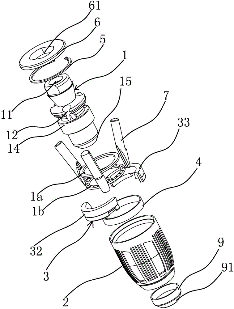
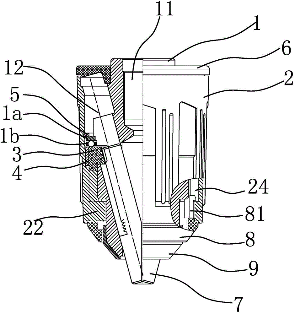
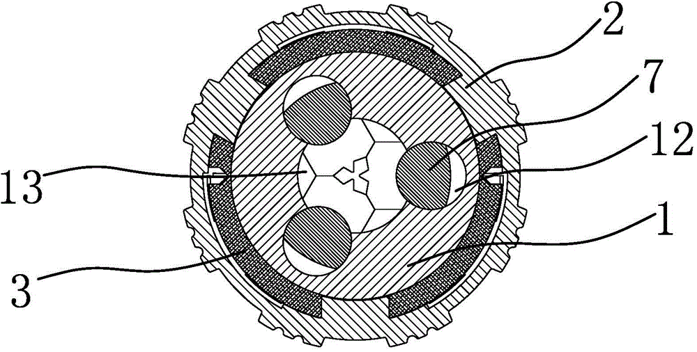
[0032] Such as Figure 1 to Figure 6As shown, the safety drill chuck includes a drill jacket 2 and a columnar drill body 1. The drill jacket 2 is sleeved on the drill body 1 and can rotate around the drill body 1. A slideway 12 inclined toward the lower end of the drill body 1, the slideway 12 is a chute or a slanted hole, in this example, a chute is used, and each slideway 12 is provided with a jaw that can slide in the slideway 12 7. There is an incomplete external thread on the jaw 7. The external thread is located on one side of the jaw 7 and matches the internal thread of the nut 3. There is also a joint between the drill chuck 2 and the jaw 7. The nut 3 is screwed together, the lower end surface of the nut 3 is prov...


PUM


Abstract

The invention provides a safety drill chuck, and belongs to the technical field of machines. The safety drill chuck achieves the aims of improving the safety and effectively guaranteeing torque transmission when clamping jaws in the drill chuck are adjusted. The safety drill chuck of the improved structure comprises a drill clamping sleeve and a cylindrical drill body. The drill clamping sleeve is arranged on the drill body in a sleeving mode and can rotate around the drill body. A plurality of sliding ways inclined towards the lower end of the drill body are distributed in the drill body in the circumferential direction. Clamping jaws capable of sliding in the sliding ways are arranged in the sliding ways. A nut in threaded connection with the clamping jaws is further arranged between the drill clamping sleeve and the clamping jaws. Grooves are formed in the lower end face of the nut, and convex keys are arranged on the inner wall of the drill clamping sleeve and connected to the interiors of the grooves in a clamped mode. A back cover is further fixedly arranged at the upper end of the drill body. The upper end of the drill clamping sleeve can abut against the back cover. The safety drill chuck of the improved structure is high in safety performance and even and stable in torque transmission.

Description

technical field [0001] The invention belongs to the technical field of machinery and relates to a drill chuck, in particular to a drill chuck which is not easy to fall off and has high safety performance. Background technique [0002] Drill chuck is a tool often used in the field of mechanical processing, used to clamp the drill bit, usually composed of drill body, jaws, drill jacket, and back cover. The three jaws are respectively installed in the three slideways of the drill body. By rotating the drill chuck, the external threads on the jaws match the internal threads on the drill chuck to realize the oblique movement of the jaws, and the precise automatic positioning. Usually a drill chuck can be equipped with different drilling tools (such as center drill, drill bit, reamer, tap, etc.). In the prior art, in order to ensure that the drilling tools can be clamped without loosening, most of them are through If the positioning screw is fastened, the loosening and falling of...

Claims


Application Information

Patent Timeline
IPC IPC(8): B23B51/12
CPCB23B51/12B23B2251/02
Inventor 王乾邵进荣陈龙
Owner ZHEJIANG CHAOLI MECHANICAL TOOLS
Learn More