
Oil pump spur gear shaft machining clamp

A wheel shaft and fixture technology, applied in the direction of manufacturing tools, components with teeth, metal processing equipment, etc., can solve the problems of not being able to process the teeth of the gear part, reduce the yield of finished products, increase the production cost, etc., and achieve easy disassembly, The effect of improving flexibility

Inactive Publication Date: 2015-08-12
天津市中马骏腾精密机械制造有限公司
View PDF0 Cites 0 Cited by
  • Summary
  • Abstract
  • Description
  • Claims
  • Application Information

AI Technical Summary

Problems solved by technology

[0004] However, usually the ejector rod clamps the blank of the spur gear shaft of the oil pump in a point-contact manner through the top of its front end. In this way, when the ejector rod is rotated to roll and form the teeth, due to the point contact with the top, the oil pump directly The blank of the gear shaft sometimes rotates, which affects the processing more. Sometimes the teeth of the gear part cannot be processed through rolling, and sometimes although the teeth are processed, some parts of the teeth are damaged and scrapped, thus reducing the quality of the finished product. rate, production costs increase

Method used


Image

  • Oil pump spur gear shaft machining clamp
  • Oil pump spur gear shaft machining clamp

Examples


Embodiment Construction

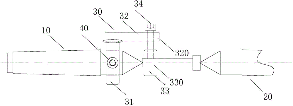
[0015] Next, a machining jig for an oil pump spur gear shaft as an example of the present invention will be described based on the drawings.

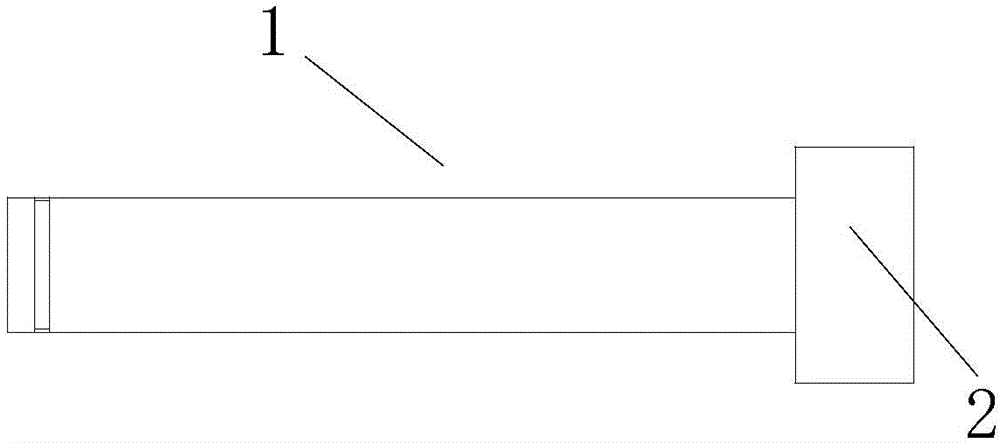
[0016] figure 1 It is a schematic side view showing the spur gear shaft of the oil pump of the present invention. figure 2 It is a schematic front view showing a machining jig for an oil pump spur gear shaft according to the present invention.

[0017] Such as figure 1 As shown, the spur gear shaft of the oil pump of the sewing machine includes a shaft part 1 and a gear part 2 . When processing such a gear shaft, the blank of the spur gear shaft of the oil pump is usually clamped between two ejector pins, and then the teeth of the gear part are rolled out while the ejector pin is rotated by a hobbing tool.

[0018] Such as figure 2 As shown, the processing fixture of the spur gear shaft of the oil pump of the present invention has a left push rod 10 and a right push rod 20 whose axes are on the same straight line, and a fixing mem...


PUM


Abstract

The invention provides an oil pump spur gear shaft machining clamp which comprises a left ejector rod and a right ejector rod. The axes of the left and right ejector rods are located on the same straight line. A fixing component is connected to the left or right ejector rod and comprises a fixing ring, a connecting arm, a positioning ring and a fastening bolt. The fixing ring can cover the portion near the tip of the left or right ejector rod. The connecting arm is connected with the circumferential face of the fixing ring. The positioning ring is connected with the free end of the connecting arm through the fastening bolt in the mode that the axis of a through hole of the positioning ring and the axes of the left and right ejector rods are located on the same straight line, and the fastening bolt can extend into the through hole in the positioning ring from the circumferential face of the positioning ring.

Description

technical field [0001] The invention relates to a fixture, in particular to a machining fixture for a spur gear shaft of an oil pump. Background technique [0002] At present, sewing machines are widely used in the garment manufacturing industry, especially large-scale sewing machines for factories, which are more widely used in mass-manufacturing garment production enterprises. In such sewing machines, in order to drive the sewing machine to operate, it is necessary to install an oil pump. The oil pump spur gear shaft is an indispensable component of the oil pump. [0003] Such as figure 1 As shown, the oil pump spur gear shaft of the sewing machine includes a shaft part 1 and a gear part 2. When processing such a gear shaft, the blank of the oil pump spur gear shaft is usually clamped between two ejector rods, and then hobbed The cutter rolls out the teeth of the gear part while rotating the ejector pin. [0004] However, usually the ejector rod clamps the blank of the ...

Claims


Application Information

Patent Timeline
IPC IPC(8): B23F23/06
Inventor 杜辰张钧王文春安明
Owner 天津市中马骏腾精密机械制造有限公司
Learn More