An automatic clamping and turning device for stamping I-shaped wheels

A technology of automatic clamping and turning device, applied in auxiliary devices, manufacturing tools, metal processing equipment, etc., can solve the problems of unstable welding quality, long welding time, low production efficiency, etc., to improve production speed and quality, production High efficiency and the effect of improving production efficiency

Active Publication Date: 2017-04-12
ZHANGJIAGANG DONGHANG MACHINERY
View PDF7 Cites 0 Cited by
  • Summary
  • Abstract
  • Description
  • Claims
  • Application Information

AI Technical Summary

Problems solved by technology

[0002] At present, when processing the I-shaped wheel for winding, manual welding is generally used, and the production efficiency is low
In addition, during processing, since the two sides of the I-shaped wheel are to be welded along the circumferential direction, the whole welding process needs to adjust the position many times to weld it, the welding time is long, the labor intensity is high, and the welding quality is unstable; moreover, due to Poor welding working environment can easily cause burns to welders

Method used


Image

  • An automatic clamping and turning device for stamping I-shaped wheels
  • An automatic clamping and turning device for stamping I-shaped wheels

Examples


Embodiment Construction

[0013] The present invention will be further described in detail below with reference to the drawings and specific embodiments.

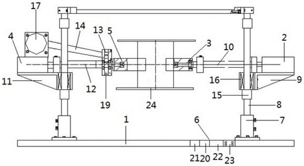
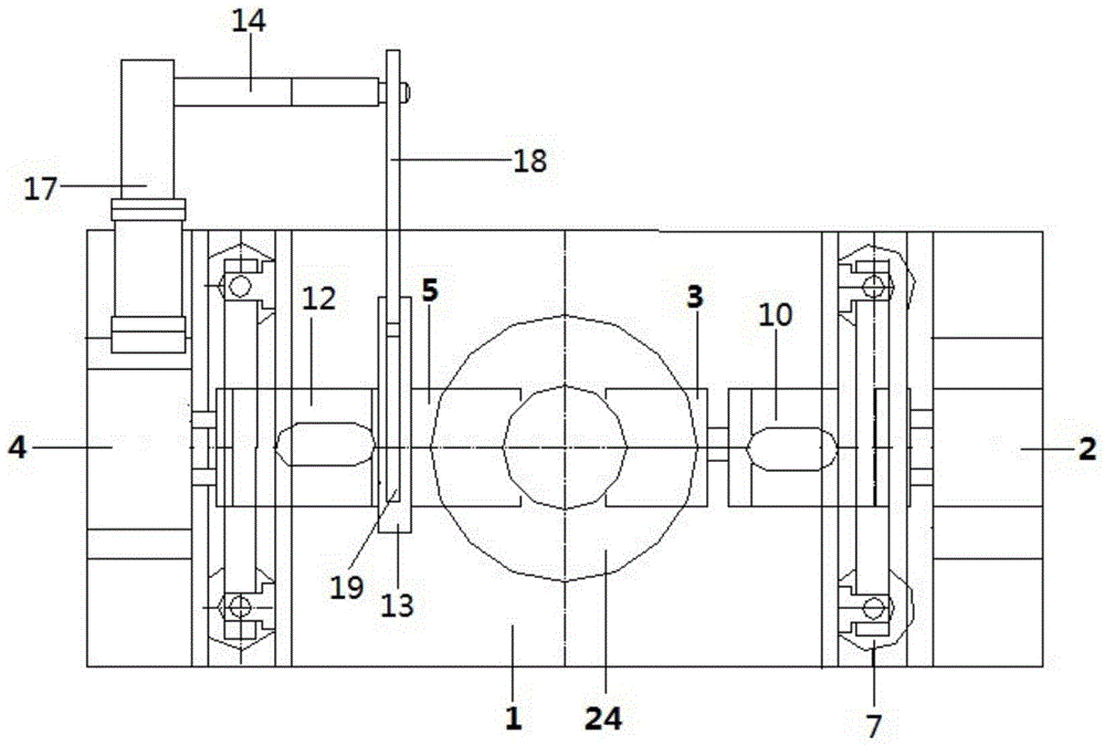
[0014] Such as Figure 1-2 As shown, an automatic clamping and turning device for stamping spools provided by the present invention includes a bottom plate 1, a double-bar cylinder 2, a passive turning mechanism 3, a rotary cylinder 4, an active clamping turning mechanism 5, and a control mechanism 6. Both the left and right ends of the bottom plate 1 are fixed with a sliding rod fixing seat 7, and a sliding rod 8 is fixed on the sliding rod fixing seat 7, and a top plate is arranged above the sliding rod 8. The bottom plate 1 is rectangular, and the bottom plate 14 A sliding rod fixing seat 7 is fixed on each corner. The double-rod cylinder 2 is arranged between the two sliding rods 8 on the right side. The double-rod cylinder 2 passes through the cylinder bracket 9 and the two sliding rods 8 on the right side. The rotary cylinder 4 is connected to t...


PUM


Abstract

The invention relates to an automatic clamping and turning device for spool stamping, which comprises a base plate, a double-rod cylinder, a passive turning mechanism, a rotating cylinder, an active clamping and turning mechanism and a control mechanism, fixed sliding rod bases are fixed at the left end and right end of the base plate, sliding rods are fixed on the fixed sliding rod bases, the double-rod cylinder is connected with the right sliding rod through a first cylinder holder, the rotating cylinder is connected with the left sliding rod through a second cylinder holder, the passive turning mechanism is connected with the double-rod cylinder through a first connector, the active clamping and turning mechanism is connected with the rotating cylinder through a second connector, a turning shell is connected between the second connector and the active clamping and turning mechanism, and the rotating cylinder is connected with the turning shell through a turning pull rod. The adopted automatic clamping and turning device for spool stamping has the advantages of simple and reasonable structure, convenience in use, stable quality, time and labor saving, high production efficiency, safety, reliability and the like.

Description

Technical field [0001] The invention relates to a clamping and turning device, in particular to an automatic clamping and turning device for a stamping spool. Background technique [0002] At present, manual welding is generally used when processing spools for winding, and the production efficiency is low. In addition, during processing, since welding is performed on both sides of the spool in the circumferential direction, the entire welding process requires multiple adjustments to weld it. The welding time is long, the labor intensity is high, and the welding quality is unstable; moreover, due to Poor welding working environment can easily cause welders to burn. Summary of the invention [0003] The purpose of the present invention is to overcome the defects in the prior art, and provide a stamping spool automatic clamping and turning device with simple and reasonable structure, convenient use, no manual operation, stable quality, time and labor saving, and high production effi...

Claims


Application Information

Patent Timeline
Patent Type & Authority Patents(China)
IPC IPC(8): B23K37/047
CPCB23K37/047
Inventor 顾建东
Owner ZHANGJIAGANG DONGHANG MACHINERY
Why Eureka
Try Eureka