Design scheme of intelligent locking apparatus for center control lock

A design scheme and intelligent technology, applied in the direction of building locks, vehicle locks, locks, etc., can solve the problems of fake locks, insecurity of vehicles, and the failure of the car to get the order to lock the door, so as to improve security and modernity. strong effect

Active Publication Date: 2015-08-12
CHONGQING NINGLAI SCI & TRADE
View PDF7 Cites 4 Cited by
  • Summary
  • Abstract
  • Description
  • Claims
  • Application Information

AI Technical Summary

Problems solved by technology

The existing problems are: 1. The operation is inconvenient. After the car door is closed, the remote control key must be taken out and pressed to put in the remote control key.
2. It is not safe enough. When criminals use a car remote control jammer with sufficient power nearby, it can interfere with the signal of the car remote control and make it malfunction.
Since the jammer is not limited by the types of vehicles and remote controls when it is used, fixed codes, special codes, and rolling codes can interfere. As long as the interference power is large enough, any model can interfere, so that the car cannot be locked. command, resulting in the false lock of the vehicle, which is unsafe and causes great hidden dangers
What's more, some lawbreakers can also use a special electronic device called a "duplicator". When the owner is using the remote control to lock the lock, this electronic device can capture the radio frequency signal and password signal of the remote control. , criminals will use this instrument to safely and boldly copy the password signal for unlocking and stealing

Method used


Image

  • Design scheme of intelligent locking apparatus for center control lock
  • Design scheme of intelligent locking apparatus for center control lock
  • Design scheme of intelligent locking apparatus for center control lock

Examples


Embodiment Construction

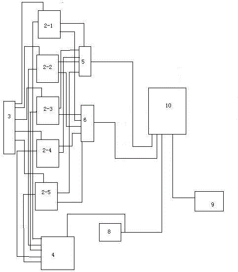
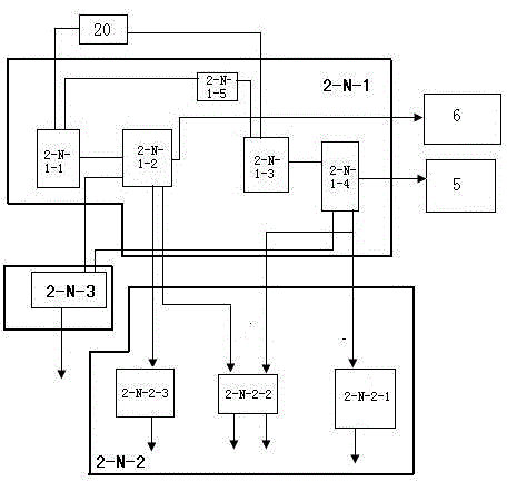
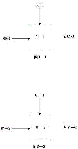
[0118] figure 1 , 2 , 3, 4, , 5, 6, 7, 8, 9 represent a design schematic diagram of an intelligent central control lock locking device and represent a specific implementation method.

[0119] (1) Make the electronic control board.

[0120] First of all, according to the relationship indicated in each figure, a design scheme of an intelligent central locking locking device: consists of a display circuit, a basic door frame unit, an input system unit, an automatic input identification circuit unit, a repair identification correction circuit unit, and an input locking system. Unit, unlocking circuit unit, execution control circuit unit, power intelligent management circuit unit, and battery power supply make up related electronic control boards.

[0121] Each door corresponds to a door frame, and each door and its corresponding frame form a basic door frame unit, and each basic door frame unit is equipped with an input system unit.

[0122] Input system unit: composed of autom...


PUM


Abstract

The present invention discloses a design scheme of an intelligent locking apparatus for a center control lock and belongs to the technical field of automotive electrical appliances. The intelligent locking apparatus comprises display circuits, basic automobile doorframe units, input system units, an automatic input identification circuit unit, a restoration identification correction circuit unit, an input locking unit, a releasing and unlocking circuit unit, an execution control circuit unit, a power supply intelligent management circuit unit and a battery power supply. One input system unit is mounted in each basic automobile doorframe unit; each input system unit comprises an automation detection circuit unit, an integrated input circuit unit and an OR gate opening circuit. According to the design scheme, the automotive center control lock in an automobile is automatically locked after the automobile door closing process is finished; an alarm is automatically put into the apparatus; the scheme is also capable of automatically detecting operation states of important parts of the apparatus in the automobile door closing process, automatically detecting fault parts in cases of faults, displaying results of the state content of the detected faults, automatically correcting the faults in a certain time and ensuring safety of the automobile.

Description

technical field [0001] The invention belongs to the technical field of automobile electric appliances. Background technique [0002] At present, the input of the central control lock and alarm system of the car is generally operated manually, that is, after all the doors are closed, the remote control key is taken out, and the remote control key is pressed to lock the central control lock of the car door and the alarm system is activated. The problems that it exists are: 1, the operation is inconvenient, after the car door is closed, the remote control key must be taken out and pressed to put in the remote control key. 2. It is not safe enough. When criminals use a car remote control jammer with sufficient power nearby, it can interfere with and intercept the signal of the car remote control, causing it to fail. Since the jammer is not limited by the types of vehicles and remote controls when it is used, fixed codes, special codes, and rolling codes can interfere. As long a...

Claims


Application Information

Patent Timeline
Patent Type & Authority Applications(China)
IPC IPC(8): E05B77/14E05B77/28E05B83/36
Inventor 宁永敭宁娅姗
Owner CHONGQING NINGLAI SCI & TRADE
Why Eureka
Try Eureka