
A high-resolution optical fiber strain sensor and its measuring method

A fiber-optic strain, high-resolution technology, applied in measurement devices, instruments, optical devices, etc., can solve the problems of slow response speed and low resolution, and achieve reliable operation, high response rate, and high strain resolution. Effect

Active Publication Date: 2018-07-03
UNIV OF SCI & TECH OF CHINA
View PDF6 Cites 0 Cited by
  • Summary
  • Abstract
  • Description
  • Claims
  • Application Information

AI Technical Summary

Problems solved by technology

[0004] The purpose of the present invention is to provide a high-resolution optical fiber strain sensor and measurement method, which can solve the problem of low resolution of traditional optical fiber strain sensors, and overcome the slow response speed of sensors based on vortex beams in rapidly changing environments. shortcoming

Method used


Image

  • A high-resolution optical fiber strain sensor and its measuring method
  • A high-resolution optical fiber strain sensor and its measuring method
  • A high-resolution optical fiber strain sensor and its measuring method

Examples


Embodiment Construction

[0031] The following provides a clear and complete description of the technical solutions in the embodiments of the present invention with reference to the accompanying drawings in the embodiments of the present invention. Obviously, the described embodiments are only a part of the embodiments of the present invention, rather than all the embodiments. Based on the embodiments of the present invention, all other embodiments obtained by those of ordinary skill in the art without creative work shall fall within the protection scope of the present invention.

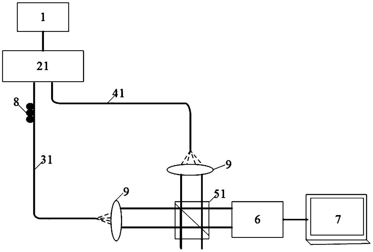
[0032] The strain sensor described in the embodiment of the present invention is based on the Mach-Zehnder interferometer structure. The vortex beam generated by the reference arm and the fundamental mode Gaussian beam generated by the sensing arm interfere with each other to form spiral interference fringes. The strain will cause the rotation of the spiral interferogram, which is then recorded by the high-speed linear CCD camer...


PUM


Abstract

The invention discloses a high-resolution optical fiber strain sensor and a measurement method. First, the output light of a narrow-band light source is transmitted to the optical beam splitter; the optical beam splitter performs beam splitting at an energy ratio of 1:1, wherein one The output beam is transmitted to the vortex optical converter as a reference arm; the other output beam is transmitted to the sensing optical path as a sensing arm; the output beams of the reference arm and the sensing arm are completed by the optical beam combiner Interference: After the interference pattern is collected by the linear array CCD camera, it is transmitted to the processing terminal for digital image processing, and the strain variation information is demodulated from the interference pattern. The optical fiber strain sensor has extremely high strain resolution, and because of the extremely high response rate due to the use of the linear array CCD camera, it can also ensure the reliable operation of the system under the condition of high strain change rate.

Description

Technical field [0001] The invention relates to the technical field of optical fiber sensing, in particular to a high-resolution optical fiber strain sensor and a measurement method. Background technique [0002] Strain sensing is widely used in the field of geosciences and large-scale engineering inspection, and in some occasions, the resolution of strain sensing is very high (such as earthquake precursor prediction requires a resolution higher than 10 -9 Magnitude). At present, strain measurement is mostly realized by electrical sensors, which have the advantages of low cost and better resolution. However, due to its disadvantages such as zero drift, susceptibility to electromagnetic environment interference, and small dynamic range, the application development is subject to many restrictions. Strain sensors based on optical fiber technology can not only overcome the shortcomings of traditional electrical strain sensors, but also facilitate networking and monitoring in harsh en...

Claims


Application Information

Patent Timeline
Patent Type & Authority Patents(China)
IPC IPC(8): G01B11/16
Inventor 陈林勋朱冰杨利
Owner UNIV OF SCI & TECH OF CHINA
Learn More