COB type LED reflector design method

A design method and reflector technology, applied in the direction of instruments, calculations, special data processing applications, etc., can solve complex problems and the accuracy of calculation results needs to be improved

Inactive Publication Date: 2015-08-12
CHINA JILIANG UNIV
View PDF2 Cites 6 Cited by
  • Summary
  • Abstract
  • Description
  • Claims
  • Application Information

AI Technical Summary

Problems solved by technology

However, it is more complicated to use the above methods, and the accuracy of some calculation results needs to be improved.

Method used


Image

  • COB type LED reflector design method
  • COB type LED reflector design method
  • COB type LED reflector design method

Examples


Embodiment Construction

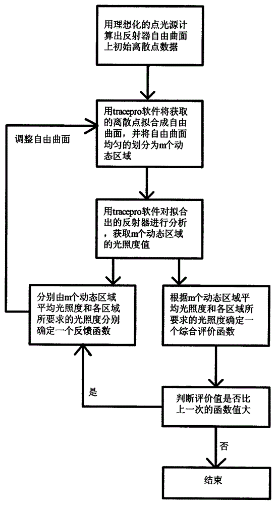
[0018] Such as figure 1 Shown is the flow chart of the design method involved in the present invention, and the concrete design steps involved are as follows:

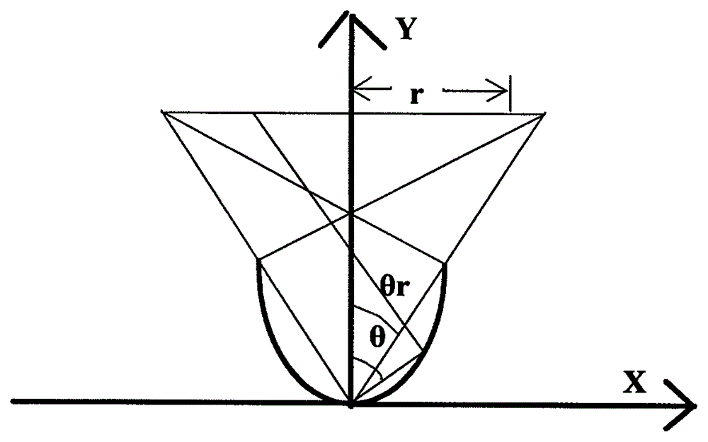
[0019] The first step of the design method involved in the present invention is to idealize the COB LED light source into a point light source, and its design principle diagram is as follows figure 2 As shown, according to the law of energy conservation, the relationship between the θ foot corresponding to the reflected part of the light and the radius r of the illuminated area is as follows:

[0020] ∫ 0 r E c · 2 πrdr = ∫ 0 θ r I · 2 π sin θdθ + ∫ θ π 2 I ...


PUM


Abstract

A COB type LED reflector design method is disclosed. The method comprises the following steps: calculating initial data of a free-form surface of a reflector by an idealized point light source; fitting acquired discrete points into the free-form surface by tracepro software and dividing the free-form surface into m dynamic regions; analyzing the free-form surface by the tracepro software and acquiring illumination values of the m dynamic regions; determining a feedback function and an evaluation function according to the luminance values of the m dynamic regions; and regulating the free-form surface according to the feedback function and the evaluation function. Relative to other COB type LED reflector design methods, the method which the present invention relates to has the advantages of high practicality, high development efficiency, high optical efficiency of the designed reflector and the like.

Description

technical field [0001] The invention relates to a method for designing an LED reflector, in particular to a method for designing a COB type LED reflector. Background technique [0002] As the latest generation of lighting sources, LED has the advantages of long life, low power consumption, and good shock resistance. Now it is gradually replacing the fluorescent lighting market and entering various fields of lighting. [0003] With the development of LED packaging technology, COB LEDs have become the mainstream LED models due to their advantages of high optical power and uniform light color. But for LED secondary optical design, the common method is to design a single LED as a point light source, which is enough to make the light distribution of ordinary packaged LEDs achieve the desired effect. However, for COB packaged LEDs, due to their large size, if they are simply treated as point light sources, the light distribution of the designed light source will definitely not ac...

Claims


Application Information

Patent Timeline
IPC IPC(8): G06F17/50
Inventor 陈亮徐珍宝沈洋苏玲爱周占春金尚忠董艳燕张淑琴
Owner CHINA JILIANG UNIV
Why Eureka
Try Eureka