
Intermediate transformer for multiple voltages output test

A technology for voltage output and testing, applied in transformers, variable transformers, inductors, etc., can solve problems such as unsightly appearance, large space occupation, and complicated use of intermediate transformers, so as to reduce potential safety hazards, reduce space occupation, and facilitate operation. Effect

Inactive Publication Date: 2015-08-12
SHANDONG ELECTRICAL ENG& EQUIP GRP INTELLIGENT ELECTRIC CO LTD
View PDF7 Cites 4 Cited by
  • Summary
  • Abstract
  • Description
  • Claims
  • Application Information

AI Technical Summary

Problems solved by technology

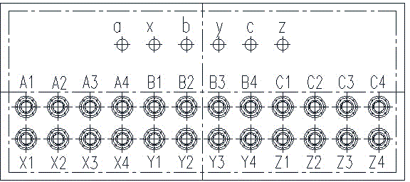
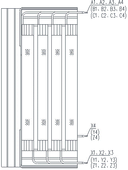
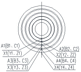
The structural schematic diagram and internal winding arrangement of the traditional test intermediate transformer are as follows: figure 1 , figure 2 and image 3 As shown, all the windings are led out, and then through serial-to-parallel conversion, Y-△ (star-delta) conversion to achieve different output voltages, which makes the use of the entire intermediate transformer very complicated, not beautiful, and takes up big space

Method used


Image

  • Intermediate transformer for multiple voltages output test
  • Intermediate transformer for multiple voltages output test
  • Intermediate transformer for multiple voltages output test

Examples


Embodiment Construction

[0016] Multiple voltage output test intermediate transformers of the present invention, such as Figure 4 and Figure 5 As shown, a new coil and lead wire structure is adopted to realize wiring inside the transformer. Firstly, the high-voltage coil is divided into four sections and axially distributed, such as Image 6 and Figure 7 As shown, the four segments are connected through a series-parallel switch 1 to achieve the purpose of adjusting the high-voltage voltage. Connect the head end of the high-voltage coil from the series-parallel switch 1 to the Y-△ switch 2 again, and realize the Y-△ conversion by adjusting the gear position. In this way, it is only necessary to lead out the nine terminals of the first end of the high-voltage coil and the first end of the low-voltage coil, and 12 different combinations of transformation ratios can be realized. For details, see Image 6 , greatly reducing the number of output terminals. Moreover, the output voltage is adjusted th...


PUM


Abstract

The invention relates to an intermediate transformer for a multiple voltages output test. The intermediate transformer comprises a high tension coil and a low tension coil. The high tension coil is divided into four sections in axial distribution so as to be led out. The four sections led out are connected through a serial-parallel change-over switch. The head and tail ends of the high tension coil are connected into a Y-delta change-over switch through the serial-parallel change-over switch. Nine terminals are led out from the head end of the high tension coil and the head and tail ends of the low tension coil. Through adoption of the intermediate transformer, high voltage adjustment is realized, twelve different transformation ratio combinations are realized, and the quantity of output terminals is sharply reduced; the switch is used for adjusting so as to output the voltage, so that the operation is convenient, wiring quantity and wiring error rate are reduced; occupied space of the whole transformer is reduced, the use ratio of the test site is increased, the quantity of electrified terminals is greatly reduced, and potential safety hazard is lowered.

Description

technical field [0001] The invention relates to an intermediate transformer for supplying power to a test circuit, and belongs to the technical field of intermediate transformers. Background technique [0002] The function of the test intermediate transformer is to supply power to the test circuit. With the diversification of transformer product types and performance parameters, and in response to the national policy of energy saving, consumption reduction, cost reduction and efficiency increase. It has become the intention of most transformer manufacturers to use one test transformer to meet various test purposes. The structural schematic diagram and internal winding arrangement of the traditional test intermediate transformer are as follows: figure 1 , figure 2 and image 3 As shown, all the windings are led out, and then through serial-to-parallel conversion, Y-△ (star-delta) conversion to achieve different output voltages, which makes the use of the entire intermedi...

Claims


Application Information

Patent Timeline
Patent Type & Authority Applications(China)
IPC IPC(8): H01F29/02H01F27/28G01R31/40
Inventor 魏彩霞李西勋张立志钟伟朱培珍杨波
Owner SHANDONG ELECTRICAL ENG& EQUIP GRP INTELLIGENT ELECTRIC CO LTD
Learn More