Automatic terminal crimping machine of RF antenna

A terminal punching machine and automatic technology, applied in the direction of circuit/collector parts, electrical components, circuits, etc., can solve the problem of not realizing automatic combination terminal punching machine, etc., and achieve the effect of high degree of automation and firm combination

Inactive Publication Date: 2015-08-12
KUNSHAN XINTAILI PRECISION COMPONENTS CO LTD
View PDF5 Cites 12 Cited by
  • Summary
  • Abstract
  • Description
  • Claims
  • Application Information

AI Technical Summary

Problems solved by technology

[0002] At present, the RF antenna in the computer mobile phone is composed of a wire head and a terminal, but there is currently no terminal punching machine that can automatically combine the two

Method used


Image

  • Automatic terminal crimping machine of RF antenna
  • Automatic terminal crimping machine of RF antenna
  • Automatic terminal crimping machine of RF antenna

Examples


Embodiment Construction

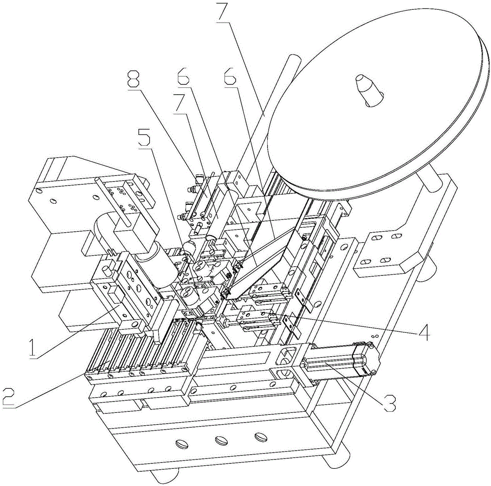
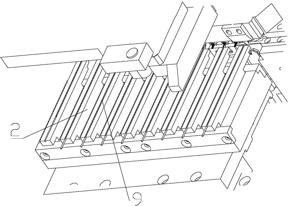
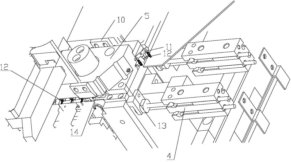
[0022] The present invention will be further described below in conjunction with the accompanying drawings and specific embodiments.

[0023] according to Figure 1-Figure 7 , the RF line automatic terminal punching machine, including a strip, is characterized in that the strip includes a strip feed section 6, a strip riveting section 6b and a strip discharge section 6c, and the strip discharge section 6c section is connected with the moving mechanism of the strip pin, and the strip riveting section is connected with the terminal cutting and bending mechanism. An integrally bent movable top block (not shown) formed by the third part 12c of the terminal; a vertically movable U-shaped block 20 for clamping the terminal is provided below the riveting section of the strip, so The terminal of the riveting section of the strip mentioned above accommodates the thread end. In fact, the thread end is mainly placed in the second part 12b of the terminal, and the whole body composed of ...


PUM


Abstract

The invention belongs to the field of electronic processing machinery, and specifically relates to an automatic terminal crimping machine of an RF antenna. The machine comprises a material belt, characterized in that the material belt comprises a material belt feeding segment, a material belt riveting segment, and a material belt discharging segment. The material belt discharging segment is connected with a material belt contact pin moving mechanism. The material belt riveting segment is connected with a terminal cutting and bending mechanism. The terminal cutting and bending mechanism is provided with a movable top block which cuts off material belt cut-off points and makes the integrated body formed by a terminal first part and a terminal third part bended. A U-shaped block which is used to clamp the terminals and can vertically move is arranged below the material belt riveting segment. The terminals of the material belt riveting segment hold wire heads. The terminal crimping machine is high in automation degree, and realizes firmly combination of terminals and wire heads.

Description

technical field [0001] The invention belongs to the field of electronic processing machinery, and in particular relates to an automatic terminal-typing machine for RF wires. Background technique [0002] At present, the RF antenna in the computer mobile phone is composed of a wire head and a terminal, but there is currently no terminal punching machine that realizes the automatic combination of the two. The wire head is composed of four layers, from the inside to the outside are sheath, braided wire, Teflon and core wire. Contents of the invention [0003] The object of the present invention is to overcome the above-mentioned problems and provide an automatic terminal-typing machine for RF antennas with a high degree of automation and a firm combination of terminals and wire ends. [0004] In order to achieve the above object, the technical solution adopted in the present invention is: an automatic RF wire terminal punching machine, including a strip, characterized in...

Claims


Application Information

Patent Timeline
Patent Type & Authority Applications(China)
IPC IPC(8): H01R43/048H01R43/055
CPCH01R43/0482H01R43/055
Inventor 张晓亮代继超
Owner KUNSHAN XINTAILI PRECISION COMPONENTS CO LTD
Why Eureka
Try Eureka