Snake bone device for endoscope

An endoscope and snake bone technology, applied in the field of snake bone devices, can solve the problems of high scrap rate, high production cost, and low production efficiency, and achieve the effects of good assembly quality, low production cost, and high production efficiency

Active Publication Date: 2015-08-19
常州延顺光电科技有限公司
View PDF10 Cites 6 Cited by
  • Summary
  • Abstract
  • Description
  • Claims
  • Application Information

AI Technical Summary

Problems solved by technology

The snake bones in the prior art include the front segment circle, the snake bone middle segment ring and the snake bone rear segment ring, and the snake bone front segment ring, the snake bone middle segment ring and the snake bone rear segment ring are sequentially riveted by rivets Connected, due to this rivet riveting connection method, the following defects are prone to occur, for example, first, the axis center of the riveting tooling and the rivet is not on the same axis or the riveting force is too large, which will cause the joint ring of the snake bone Deformation occurs at the riveting place; second, during the riveting process, if the riveting pressure is too large, the surface of the workpiece is easily damaged or the rivet is deformed or the rivet head cracks; third, the riveted workpiece is prone to riveting failure. in place, or the riveting is not strong enough; therefore, the workers' riveting skills are required to be high, which makes the production efficiency low, and it is also relatively easy to have unqualified riveting quality, and sometimes the rivets will fall off. There are many defects in the finished product and the scrap rate is high, which makes the production cost higher

Method used


Image

  • Snake bone device for endoscope
  • Snake bone device for endoscope
  • Snake bone device for endoscope

Examples


Embodiment Construction

[0028] The present invention will be further described below in conjunction with the accompanying drawings and given embodiments, but is not limited thereto.

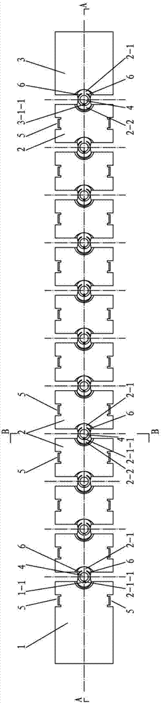
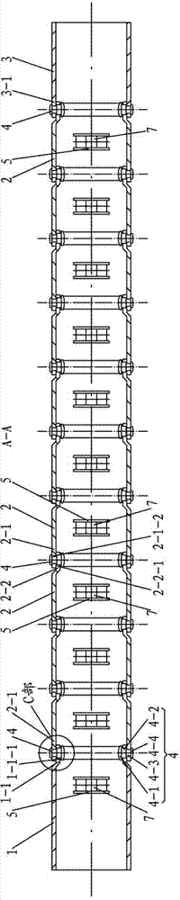
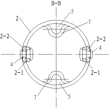
[0029] like figure 1 , 2 , 3, 4, 5, 6, 7, and 8, a snake bone device of an endoscope, including snake bone front segment circle 1, snake bone rear segment ring 3, connected to snake bone front segment ring 1 and snake bone Several snake bone middle segment rings 2 and their connecting pins 4 between the posterior segment rings 3; one end of the snake bone front segment ring 1 is provided with a rear connecting ear 1-1, and the rear connecting ear 1- 1 is provided with a rear connecting shaft hole 1-1-1; the two ends of each snake bone middle segment ring 2 are respectively provided with a first connecting ear 2-1 and a second connecting ear 2-2, the first connecting The ear 2-1 is provided with a first connecting shaft hole 2-1-2, the second connecting ear 2-2 is provided with a second connecting shaft hole 2-2-1, and...


PUM


Abstract

The invention relates to a snake bone device for an endoscope. The device comprises a snake bone front segment ring, a snake bone rear segment ring, multiple snake bone middle segment rings and connecting pin shafts, wherein the snake bone front segment ring and the snake bone rear segment ring are provided with a rear connecting lug and a front connecting lug respectively, and the rear connecting lug and the front connecting lug are provided with connecting shaft holes respectively; each snake bone middle segment ring is provided with a first connecting lug and a second connecting lug which are provided with connecting shaft holes, a clamping notch communicated with the corresponding first connecting shaft hole is formed in each first connecting lug, and the first connecting lug of one snake bone middle segment ring is connected with the second connecting lug of another snake bone middle segment ring through the corresponding connecting pin shaft; a front clamping notch communicated with the front connecting shaft hole is formed in the front connecting lug, the rear connecting lug is connected with the first connecting lug of the adjacent snake bone middle segment ring through the corresponding connecting shaft pin, the front connecting lug is connected with the second connecting lug of the adjacent snake bone middle segment ring through the corresponding connecting shaft pin, and axial threading grooves are formed in the inner walls of the snake bone front segment ring and the multiple snake bone middle segment rings respectively. According to the device, riveting is not needed, assembly is convenient, and production efficiency is high.

Description

technical field [0001] The invention relates to a snake bone device, in particular to a snake bone device used for medical flexible tube endoscopes and industrial flexible tube endoscopes. Background technique [0002] When the existing endoscope realizes head bending and changing direction at a bending angle, the built-in snake bone bends it by pulling the steel wire rope connected with the snake bone. The snake bones in the prior art include the front segment circle, the snake bone middle segment ring and the snake bone rear segment ring, and the snake bone front segment ring, the snake bone middle segment ring and the snake bone rear segment ring are sequentially riveted by rivets Connected, due to this rivet riveting connection method, the following defects are prone to occur, for example, first, the axis center of the riveting tooling and the rivet is not on the same axis or the riveting force is too large, which will cause the joint ring of the snake bone Deformation ...

Claims


Application Information

Patent Timeline
Patent Type & Authority Applications(China)
IPC IPC(8): A61B1/008
CPCA61B1/00064A61B1/00112A61B1/008G02B23/2476
Inventor 谢梦蕾谢民政
Owner 常州延顺光电科技有限公司
Why Eureka
Try Eureka