
Ground-rising type catcher for inclined mining lane

A technology for preventing sports cars and inclined lanes, which is applied in transportation and packaging, railway car body parts, and forced railway car stoppers. Effect of impact deformation, avoiding frictional damage and even fracture

Inactive Publication Date: 2015-08-19
常熟市康达电器有限公司
View PDF12 Cites 0 Cited by
  • Summary
  • Abstract
  • Description
  • Claims
  • Application Information

AI Technical Summary

Problems solved by technology

Although this patent solution can realize the technical effect summarized in paragraph 0015 of its description, it has the following two shortcomings: First, because a group of lengthy net rolls are respectively fixedly connected to a pair of net roll connecting brackets through its two ends, the The impact resistance of the middle part of the network roller to the mine car with large mass and inertia is very fragile, which affects the interception effect on the out-of-control mine car; second, when the mesh blocking mechanism is in the closed state of the mine car At this time, the mine car traction steel wire rope used to pull the mine car movement will have severe friction with the car barrier panel of the mesh retaining mechanism, which will affect the service life of the mine car traction wire rope and even break. Interference effect of wire rope

Method used


Image

  • Ground-rising type catcher for inclined mining lane
  • Ground-rising type catcher for inclined mining lane
  • Ground-rising type catcher for inclined mining lane

Examples

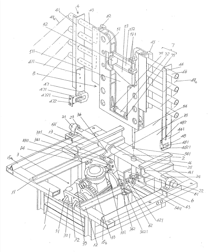
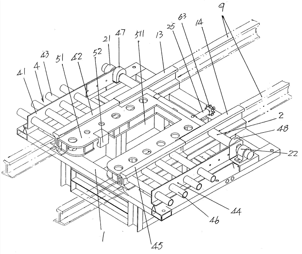

Embodiment Construction

[0024] In order to enable the examiners of the patent office, especially the public, to understand the technical essence and beneficial effects of the present invention more clearly, the applicant will describe in detail the following in the form of examples, but none of the descriptions to the examples is an explanation of the solutions of the present invention. Any equivalent transformation made according to the concept of the present invention which is merely formal but not substantive shall be regarded as the scope of the technical solution of the present invention.

[0025] In the following descriptions, all concepts involving directionality or orientation of up, down, left, right, front and rear are aimed at figure 1 As far as the location and state are concerned, the purpose is to facilitate the public's understanding, so it cannot be interpreted as a special limitation on the technical solution provided by the present invention.

[0026] See figure 1 , a frame-shaped ...


PUM


Abstract

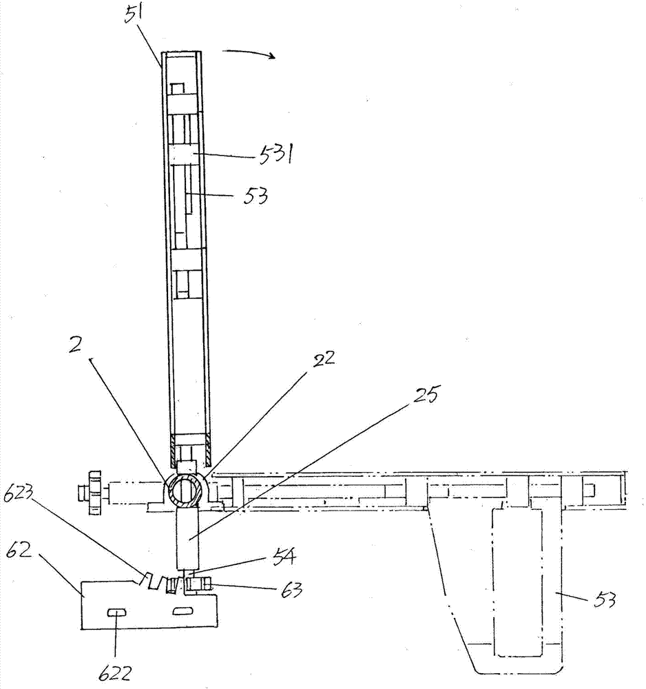
A ground-rising type catcher for an inclined mining lane belongs to the technical field of mining safety protection facilities. The ground-rising type catcher for the inclined mining lane comprises a chassis, a spindle, a spindle power drive mechanism, and a backstop mechanism; the ground-rising type catcher further comprises a backstop reinforcing mechanism, a door shaft drive mechanism and a mine car steel traction rope guide mechanism. A left rail bridge seat, a right rail bridge seat, a left linking rail and a right linking rail are fixed in the upper portion of the chassis. The left end of the spindle is supported on the left side of the chassis after passing through the left linking rail; and the right end of the spindle is supported on the right side of the chassis after passing through the right linking rail. The spindle power drive mechanism is installed on the chassis and is connected with the middle of the spindle. The left side of the backstop mechanism is connected with the left end of the spindle; and the right side of the backstop mechanism is connected with the right end of the spindle. The backstop reinforcing mechanism is connected with the backstop mechanism. The door spindle drive mechanism is arranged on the chassis and is connected with the backstop reinforcing mechanism. The mine car steel traction rope guide mechanism is arranged at the lower portion of the backstop reinforcing mechanism. The strength of the backstop mechanism is increased, thereby preventing the mine car from being deformed or even damaged by impact; and the mine car steel traction rope can be well guided, thereby preventing the rope from being damaged or even broken by friction.

Description

technical field [0001] The invention belongs to the technical field of mine safety protection facilities, and in particular relates to a ground-up anti-car device for mine inclined roadways, which is used for intercepting out-of-control mine cars. Background technique [0002] In coal mine shafts, metal mines and non-metallic mines, etc., in single-track or double-track lifting and transport inclined lanes with an inclination angle of less than 30° above or below the mine, according to safety regulations such as the first paragraph of Article 370 of my country's coal mine safety regulations It is stipulated that an anti-running device should be installed to prevent a mine car that is in normal traction and moving on a single-track or double-track due to situations such as breakage of the traction wire rope, damage to the hook head, and loss of control of the winch. Said flying car), that is, the mine car lane is closed by the anti-running device, so as to avoid major accident...

Claims


Application Information

Patent Timeline
Patent Type & Authority Applications(China)
IPC IPC(8): B61K7/16
CPCB61K7/16
Inventor 宗建康
Owner 常熟市康达电器有限公司
Learn More