
Tower crane structure with weight detection

A technology of weight detection and tower crane, which is applied in cranes, load hanging components, transportation and packaging, etc., can solve the problems of safety and hidden dangers of steel cables, and achieve the effect of safe use and stable connection

Active Publication Date: 2015-08-19
上海水纹信息科技有限公司
View PDF6 Cites 12 Cited by
  • Summary
  • Abstract
  • Description
  • Claims
  • Application Information

AI Technical Summary

Problems solved by technology

In the actual operation process, when the hook is connected to the heavy object, the tension of the steel cable of the hoist will change at the moment the heavy object is hoisted and the heavy object is in the air, but the tensile performance of the steel cable is constant. Therefore, Even if the gravity of some heavy objects is within the tensile range of the cable, the gravity of the heavy object may exceed the rated load of the cable at the moment of lifting or under the influence of wind in the air, and there are potential safety hazards in the overload state of the cable.

Method used


Image

  • Tower crane structure with weight detection
  • Tower crane structure with weight detection
  • Tower crane structure with weight detection

Examples


Embodiment Construction

[0018] The present invention will be further described below in conjunction with accompanying drawing and specific embodiment:

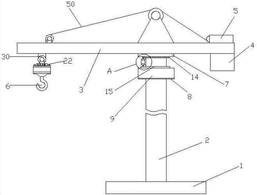
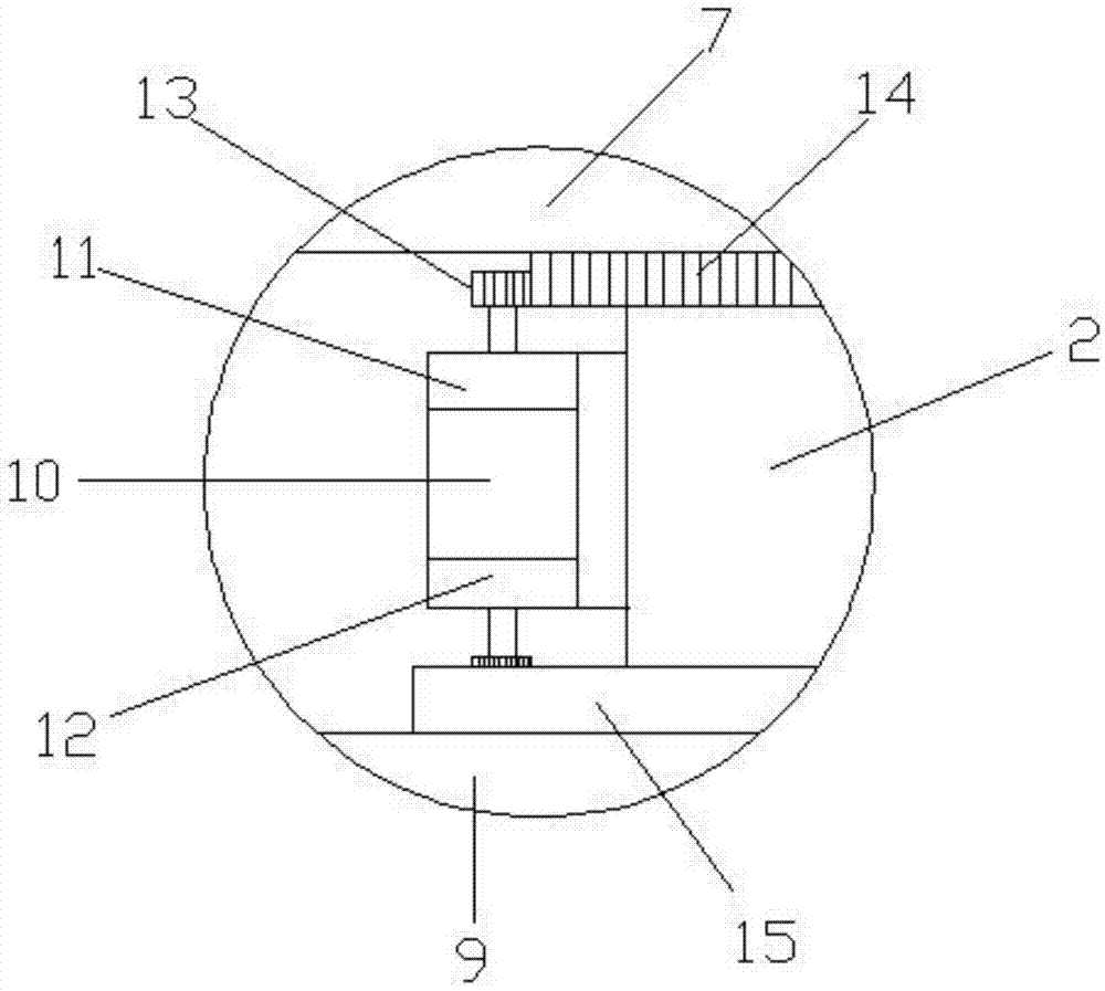
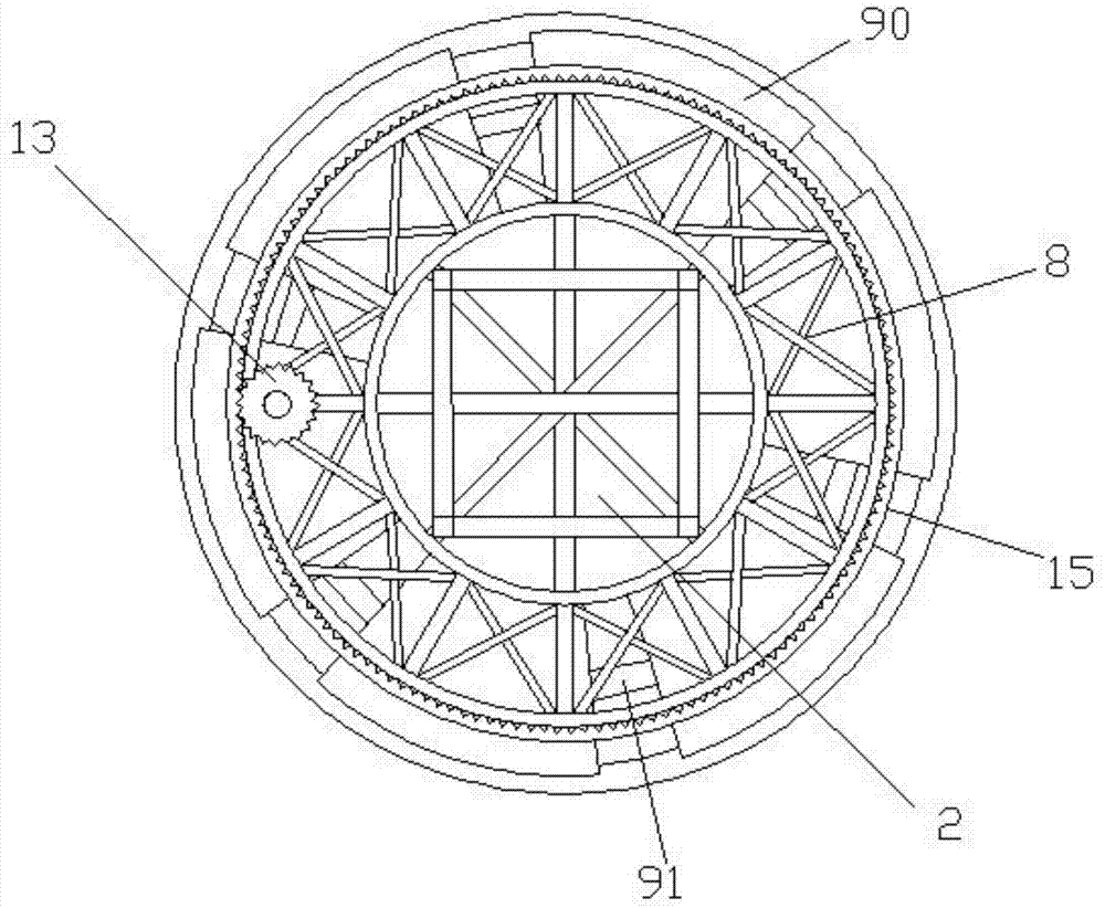
[0019] Such as figure 1 A safe tower crane structure shown includes a base 1, a tower body 2 vertically fixed on the base, a boom 3 is arranged on the top of the tower body, and a counterweight base block 4 and a hoist 5 are arranged at one end of the boom. The other end of arm 3 is provided with pulley 30, and the cable 50 on the winch 5 walks around pulley 30 and is connected with boom, and the bottom of cable 50 is provided with hook 6, and the middle part of boom 3 is provided with turntable 7, and turntable 7 and The rotating connection between the tower body 2 tops, such as figure 2 As shown, the upper end of the tower body 2 is positioned at the lower side of the turntable to be provided with an annular steel cage 8, and the annular steel cage is provided with a balance weight ring 9 that can rotate around the tower body, and the center of g...


PUM


Abstract

The invention relates to the technical field of engineering hoisting equipment and discloses a tower crane structure with weight detection. The tower crane structure comprises a base and a tower body vertically fixed on the base, wherein a suspension arm is arranged at the top of the tower body; a weight base block and a winch are arranged at one end of the suspension arm; the other end of the suspension arm is provided with a pulley; a steel rope on the winch winds around the pulley to be connected with the suspension arm; a hook is arranged under the steel rope; a rotary table is arranged in the middle of the suspension arm and is rotationally connected with the top of the tower body; the pulley is provided with a connection shaft; the bottom of the hook is provided with a connection plate; a supporting ring is arranged at the outer end of the connection plate; a cover plate is arranged at the outer end of the supporting ring; a central hole is formed in the center of the cover plate; the outer end of the connection shaft is provided with an anti-releasing baffle; a pressure sensor is arranged between the anti-releasing baffle and the inner end of the cover plate; and the outer end of the cover plate is provided with an alarm lamp connected with the pressure sensor. The tower crane structure can be used for detecting the weight of objects in real time so that whether the tension of an object on the steel rope is in a steel rope load range or not is judged and the utilization is relatively safe.

Description

technical field [0001] The invention relates to the technical field of engineering lifting equipment, in particular to a tower crane structure with weight detection. Background technique [0002] Tower crane is the most commonly used lifting equipment on construction sites, also known as tower cranes. It is used to lift construction materials such as steel bars, wood corrugated, concrete, and steel pipes. Tower cranes are an indispensable equipment on construction sites. The function of the tower suspension tip is to bear the upper load transmitted from the jib stay rope and the balance jib stay rope, and transmit it to the tower body structure directly through the turntable through the structural components such as the slewing tower, turntable, and seat. The top of the self-elevating tower has Truncated cone column, forward or backward inclined truncated cone column, herringbone frame and diagonal brace. A common tower crane generally consists of a base, a tower body, a bo...

Claims


Application Information

Patent Timeline
Patent Type & Authority Applications(China)
IPC IPC(8): B66C23/88B66C23/76B66C13/16
CPCB66C13/16B66C23/76B66C23/88B66C2700/03
Inventor 马妮
Owner 上海水纹信息科技有限公司
Learn More