
Crane winding device with steel wire rope straining mechanism

A technology of tensioning mechanism and hoisting device, applied in the direction of hoisting device, spring mechanism, etc., can solve the problems of reducing the service life of steel wire rope, skipping or slipping wire rope arrangement, loose and disordered, etc.

Inactive Publication Date: 2015-08-19
SHANDONG JIANZHU UNIV
View PDF6 Cites 13 Cited by
  • Summary
  • Abstract
  • Description
  • Claims
  • Application Information

AI Technical Summary

Problems solved by technology

When the prefabricated block is unloaded, it needs to be moved from a certain height to a lower height. When the hook of the hoisting device in the lifting device is connected to the heavy object, the wire rope is not in a tensioned state. If the heavy object is lifted at this time, The tension of the wire rope increases sharply, reducing the service life of the wire rope. At the same time, due to the slackness of the wire rope, the wire rope is prone to jumping or slipping when it is wound on the drum, resulting in loose and disorderly arrangement of the wire rope; Reversed directional movement, after hoisting, slowly lower to a lower height. If the loose section of the steel wire rope on the drum is released during the slow descent, and the weight descends faster, the pulling force of the steel wire rope will still increase sharply. If the loose section of the steel wire rope on the drum is Its disorderly winding makes it impossible to loosen, and the heavy object will be suspended in the air and cannot fall

Method used


Image

  • Crane winding device with steel wire rope straining mechanism

Examples


Embodiment Construction

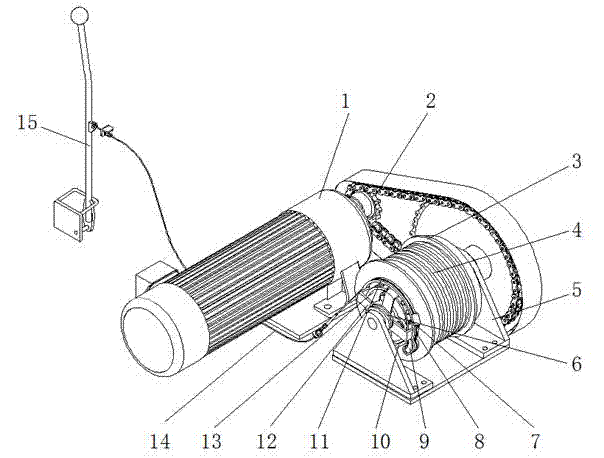
[0010] Such as figure 1 As shown, the hoisting device of the crane with the steel wire rope tensioning mechanism of the present invention comprises a reel part, a motor 1 and a deceleration system 2, in the reel part, the steel wire rope 4 is wound on the reel 3 through one end of the pulley block, and the other end is connected to the suspension hook, and the reel The drum 3 is supported by the bearing housing 5, and the motor 1, the reduction system 2 and the transmission shaft of the reel 3 are connected in sequence. A one-way bearing is installed in the reel 3 , the inner ring of the one-way bearing cooperates with the transmission shaft, and the outer ring cooperates with the reel 3 . A wire rope tensioning mechanism is installed on one side of the reel 3. The wire rope tensioning mechanism is composed of a ratchet 13, a pawl 9, a bracket 12 and a limit block 10. The ratchet 13 is connected to the end cover of the reel 3 by bolts. The outer periphery of the ratchet 13 Th...


PUM


Abstract

The invention discloses a crane winding device with a steel wire rope straining mechanism. The crane winding device with the steel wire rope straining mechanism comprises a winding drum part, a motor and a speed reduction system, a one-way bearing is installed in a winding drum, the inner ring of the one-way bearing is matched with a transmission shaft, and the outer ring of the one-way bearing is matched with the winding drum; the steel wire rope straining mechanism is installed on one side of the winding drum and comprises a ratchet wheel, a pawl, a support and a limiting block, the ratchet wheel is connected to an end cap of the winding drum, ratchet wheel slots are formed in the periphery of the ratchet wheel at intervals, the pawl is installed on the support, embedded into the ratchet wheel slots under the action of a compressed spring and meshed with the ratchet wheel slots, the support is provided with an arc-shaped section which is provided with a groove, a brake cable is placed in the groove, one end of the brake cable is fixedly connected with the support, and the other end of the brake cable is connected with a manipulation handle; when the handle is pressed down, the support is made to rotate in the tension direction, the winding drum rotates along with the support to strain the steel wire rope; a torsional spring is installed between the support and a bearing seat, when the handle is loosened, the support returns to the original position under the action of the torsional spring, and the limiting block is installed on the bearing seat to make the pawl break away from the ratchet wheel slots. According to the crane winding device with the steel wire rope straining mechanism, the structure is compact, the design is reasonable, and straining of the steel wire rope is safe and reliable.

Description

technical field [0001] The invention belongs to the technical field of cranes, in particular to a hoisting device for a crane with a wire rope tensioning mechanism. Background technique [0002] In order to save resources and implement green construction, prefabricated concrete blocks of certain specifications are often used for temporary roads and site paving on construction sites, but it is difficult to solve the problems of unloading and laying in place after these prefabricated blocks with rated weight arrive at the site. Considering that the construction site needs small and easy-to-operate lifting equipment to complete temporary road and site laying, the hoisting device of the lifting equipment should also have a compact structure. When the prefabricated block is unloaded, it needs to be moved from a certain height to a lower height. When the hook of the hoisting device in the lifting device is connected to the heavy object, the wire rope is not in a tensioned state. I...

Claims


Application Information

Patent Timeline
Patent Type & Authority Applications(China)
IPC IPC(8): B66D1/42
CPCB66D1/42
Inventor 张明勤马荣全原政军苗冬梅姚玉善孟宪举王晴刘昆金钢韩立芳
Owner SHANDONG JIANZHU UNIV
Learn More