Island wind-driven power generator with hoop valve and nickel alloy pistons

A nickel alloy and clamp technology, applied in the field of power generation auxiliary devices, can solve problems such as loss and large resistance, and achieve the effect of eliminating cooling accidents and reducing expensive maintenance costs

Inactive Publication Date: 2015-08-19
WENZHOU ZHANGHENG SCI & TECH SERVICE CO LTD CO LTD
3 Cites 1 Cited by

AI-Extracted Technical Summary

Problems solved by technology

Currently used one-way valves, such as: steel ball type, valve type and gravity type, have the main disadvantages: a large resistance loss due to the spring installed ...

Method used

(1), platform hinge 444 is connected with one end of hoop piston two-way buffer 445 on the periphery of working platform 410, and the other end of hoop piston two-way buffer 445 is connected with fixed leg 446, and described The two-way buffer 445 of the clamp piston and the plane of the working platform 410 are arranged at an angle of 45 degrees to ensure that the working platform 410 is stably fixed.
(3), clamp horizontal check valve 490 is placed horizontally as a whole, and the fan-shaped cylinder 725 of the spool is located above the round hole 781 of the spool. If there is no spring or other hindering parts in the clamp horizontal check valve 490, the deformed flow channel 788 and the annular flow channel are formed between the variable flow channel cone 724 on the swing valve core 720 and the valve core fan-shaped cylinder 725. The crossing 722 communicates with the circular passage opening 721 . The application of the clamp horizontal check valve 490 can ensure the normal operation of the system equipment before the annual overhaul, eliminate the cooling accident caused by the failure of the check valve, and reduce the expensive maintenance costs that are difficult to repair in the harsh environment of islands and reefs.
The pipeline plane 753 on the clamp joint valve body 730 is close to the pipeline plane 753 on the end of the outer pipeline jo...

Abstract

The invention relates to an island or beach power generation auxiliary device, and discloses an island wind-driven power generator with a hoop valve and nickel alloy pistons. The island wind-driven power generator is characterized in that platform hinges at the circumferential edge of an operation platform are connected with upper ends of bidirectional buffers with the hoop pistons, lower ends of the bidirectional buffers with the hoop pistons are connected with fixing legs, an electro-mechanical conversion unit, an energy storage cabinet and a cooling pump are fixedly mounted on the operation platform, a connecting wire is arranged between the energy storage cabinet and the electro-mechanical conversion unit, a wind wheel rotary shaft extends out of a top cover of the electro-mechanical conversion unit, a blade rotary wheel is fixedly supported by the wind wheel rotary shaft, and the hoop horizontal check valve is further arranged between an upper section of a pump suction pipe and a lower section of a filter suction pipe in a serially connected manner. The island wind-driven power generator is characterized in that the bidirectional buffers with the hoop pistons comprise hoop piston rods, hoop piston cylinders, hoop guide outer barrels, lower-rend hoop covers, upper-end hoop covers, paired semi-open lower hoops and paired semi-open upper hoops; lower-hoop left conical surfaces and lower-hoop right conical surfaces are simultaneously matched with cylinder conical surfaces and lower-cover conical surfaces.

Application Domain

SpringsCheck valves +6

Technology Topic

Electric generatorPiston cylinder +5

Image

  • Island wind-driven power generator with hoop valve and nickel alloy pistons
  • Island wind-driven power generator with hoop valve and nickel alloy pistons
  • Island wind-driven power generator with hoop valve and nickel alloy pistons

Examples

  • Experimental program(1)

Example Embodiment

[0043] The present invention will be described in detail below with reference to the drawings and specific embodiments:
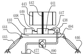
[0044] figure 1 , figure 2 , image 3 , Figure 4 , Figure 5 , Image 6 , Figure 7 , Figure 8 , Picture 9 , Picture 10 , Picture 11 , Picture 12 , Figure 13 with Figure 14 Middle: a kind of nickel alloy piston island reef wind generator with clamp valve. On the periphery of the working platform 410, there is a platform hinge 444 connected with the upper end of the clamp piston two-way buffer 445, and the lower end of the clamp piston two-way buffer 445 is connected with The fixed feet 446 are connected, the organic-electric conversion unit 441, the energy storage cabinet 448, and the cooling pump 438 are fixedly installed on the work platform 410. There is a connecting wire 449 between the energy storage cabinet 448 and the electromechanical conversion unit 441 for cooling There is a cooling duct 447 between the outlet of the pump 438 and the electromechanical conversion unit 441. On the top cover of the electromechanical conversion unit 441, a wind turbine shaft 442 extends, and the wind turbine shaft 442 fixedly supports the fan rotor 443. The cooling pump The suction port of 438 has an upper section 494 of the pump suction pipe, and a horizontal clamp check valve 490 is connected in series between the upper section 494 of the pump suction pipe and the lower section 477 of the filter suction pipe, as an improvement:
[0045] The clamp piston two-way buffer 445 includes a clamp piston rod 611, a clamp piston cylinder 613, a clamp guide outer cylinder 612, a lower end clamp cover 119, an upper end clamp cover 809 and a pair of half-open lower clamp 555 And a half-open upper clamp 333; one end of the clamp piston rod 611 is hermetically fixed with an outer sealing piston 936, the outer circular groove of the outer sealing piston 936 has a sealing ring 636 for a hole, and a sealing ring 636 for the hole A movable seal is formed between the inner holes of the clamp piston cylinder 613, the other end of the clamp piston rod 611 has a piston rod external thread 625, and the outer diameter of the piston rod external thread 625 is smaller than or equal to the clamp piston rod 611 Outer diameter size; one end of the clamp piston cylinder 613 is sealed and fixed with an inner seal piston 621, the inner groove of the inner seal piston 621 has a shaft seal ring 626, a shaft seal ring 626 and the clamp piston rod 611 A movable seal is formed between the outer circles. The other end of the clamp piston cylinder 613 has a cylinder clamp interface 191, the back of the cylinder clamp interface 191 has a cylinder cone surface 235, and the lower end clamp cover 119 has a lower cover cone on the back. Surface 253, the cylinder cone surface 235 is symmetrical to the lower cover cone surface 253; in the half-open lower clamp 555, there are lower hoop left cone surface 835 and lower hoop right cone surface 853, lower hoop left cone surface 835 and lower hoop right The tapered surface 853 cooperates with the cylinder tapered surface 235 and the lower cover tapered surface 253 at the same time; the pair of half-open lower clamp 555 is fastened by two sets of lower bolts and nuts 844 to be assembled in pairs. There is a buffer lower end 632 at the outer end of the lower end clamp cover 119; the inner hole cylindrical wall of the open end of the clamp guide outer cylinder 612 and the outer circle of the clamp piston cylinder 613 are in a sliding fit, The other end of the clamp guide outer cylinder 612 is provided with an outer cylinder clamp interface 908, the back of the outer cylinder clamp interface 908 has an outer cylinder cone surface 335, and the upper end clamp cover 809 has an upper cover cone surface 353 on the back. The cylindrical cone surface 335 is symmetrical to the upper cover cone surface 353; the upper hoop left cone surface 935 and the upper hoop right cone surface 953, the upper hoop left cone surface 935 and the upper hoop right cone surface 953 are inside the half-open upper clamp 333. At the same time, it cooperates with the cone surface 335 of the outer cylinder and the cone surface 353 of the upper cover; the paired half-open upper clamp 333 is fastened by two sets of upper bolts and nuts 944 to be assembled in pairs; the upper end There is a buffer upper end 622 on the outside of the back of the clamp cover 809; the inside of the upper clamp cover 809 is provided with a clamp screw hole 615, and the clamp screw hole 615 is tightly connected with the outer piston rod thread 625 There is a sealing gasket 222 between the cylinder clamp interface 191 on the clamp piston cylinder 613 and the lower end clamp cover 119, and the outer cylinder clamp interface 908 on the clamp guide cylinder 612 and There is also a sealing gasket 222 between the upper clamp cover 809; the first cavity 111 is formed between the outer sealing piston 936 and the lower clamp cover 119, and the outer sealing piston 936 and the The second cavity 112 is formed between the inner sealing piston 621;
[0046] The clamp piston cylinder 613 and the clamp guide cylinder 612 are made of high-strength, corrosion-resistant nickel alloy steel as a whole, and the inner seal piston 621 and the outer seal piston 936 are all made of zirconia ceramics. .
[0047] As a further improvement: figure 1 , Figure 15 , Figure 16 , Figure 17 , Figure 18 , Figure 19 , Figure 20 with Figure 21 Wherein, the clamp horizontal check valve 490 includes a cylindrical shaft 710, a swing valve core 720, a clamp joint valve body 730, a fastening screw 770, and an outer end cover 790. The clamp joint valve body 730 has an outlet bend. Tube 731 and inlet elbow 732, outlet elbow 731 and inlet elbow 732 have a valve tube plane 753 at the outer end, inside of the valve tube plane 753 is the valve tube cone table 734, and there is a pipeline plane on the end of the outer pipe joint 750 735, the pipeline plane 735 is in close contact with the valve tube plane 753, the back of the pipeline plane 735 is the pipeline cone table 754, and the pipeline cone table 754 corresponds to the valve tube cone table 734; assembled in pairs The lower half of the clamp 741 and the upper half of the clamp 742 are fastened by two sets of bolts and nuts 777. The lower half of the clamp 741 and the upper half of the clamp 742 have a valve pipe cone surface 745 and a pipeline cone surface 775. They are matched with the valve tube cone surface 734 and the pipeline cone surface 754 respectively; the inner end of the outlet elbow 731 is connected to the valve body inlet plane hard layer 738 of the clamp joint valve body 730, so The inner end of the inlet elbow 732 is connected to the valve body outlet plane hard layer 739 of the clamp joint valve body 730; the valve body inlet plane hard layer 738 and the valve body outlet plane hard layer 739 The upper edge is connected with the fan-shaped arc surface 763 of the valve body. The lower edges of the valve body inlet plane hard layer 738 and the valve body outlet plane hard layer 739 are connected with the valve body circular concave arc surface 762. There are screw holes 727 on the valve body side planes 736 on both sides of the valve body 730 of the hoop joint; the two outer end covers 790 have end cover counterbores 797 corresponding to the screw holes 727; The fastening screw 770 passes through the end cover counterbore 797 and is fastened and matched with the screw hole 727 to tighten the end cover inner plane 798 of the outer end cover 790 with the valve body side plane 736. The two outer cover shaft holes 791 on the outer end cover 790 and the two ends of the cylindrical shaft 710 are in a sealed fit; the outer circle of the cylindrical shaft 710 and the valve of the swing valve core 720 The core hole 781 can be rotated and slidingly fitted; the valve core tube end faces 789 on both sides of the swing valve core 720 are in clearance fit with the inner planes 798 of the two outer end covers 790; The spool circular pipe arc surface 782 of the spool 720 has a spool sector cylinder 725; the spool sector cylinder 725 has an annular flow passage 722 on the spool inlet liner surface 728 side. The valve core outlet liner surface 729 side of the body 725 has a circular flow passage opening 721; the annular flow passage opening 722 and the circular flow passage opening 721 are connected with a deformed flow passage 788; the deformed flow passage A five-leaf connecting rib 744 is connected between the portion of the variable flow channel cone 724 contained in 788 and the spool sector column 725; the valve tube plane 753 has a ring sealing groove 737, and the sealing groove There is a sealing ring 757 inside the 737.
[0048] The overall material of the swing valve core 720 and its variable flow channel cone 724 part and the valve core sector column 725 part are made of engineering rubber; the valve core inlet liner surface 728 and the valve core outlet liner The plate surface 729 has a ceramic liner with a thickness of 1.6 to 1.8 mm, and the ceramic liner is also made of zirconia ceramics as a whole.
[0049] The zirconia ceramic is made of (Zirconium dioxide) as the base material, with the mineralizer MgO (magnesium oxide), (Barium carbonate) and combined clay, and the weight percentage of each component is : 92.2~92.8%; MgO: 2~3%; :2~3%; combined clay: 2.2~2.8%;
[0050] The thickness of the valve body inlet plane hard layer 738 and the valve body outlet plane hard layer 739 is 1.5 to 1.7 mm, the valve body inlet plane hard layer 738 and the valve body outlet plane The hard layer 739 is made of nickel alloy steel, which is composed of the following components by weight percentage: Ni (nickel): 12-14%, Cu (copper): 6.4-6.6%, W (tungsten): 5.6~5.8%, Ti (titanium): 4.2~4.4%, Sn (tin): 3.4~3.6%, Zn (zinc): 2.2~2.4%, C (carbon): 1.6~1.8%, Cr (chromium): 1.4~1.6%, the balance is Fe (iron) and unavoidable impurities; the weight percentage content of the impurities is: Si (silicon) less than 0.20%, Mn (manganese) less than 0.25%, S (sulfur) less than 0.01%, P (phosphorus) is less than 0.015%; the main performance parameters of the nickel alloy hard wear-resistant coating material are: Rockwell hardness HRC value is 45-47.
[0051] Further preferred in the embodiment:
[0052] The inner diameter of the clamp piston cylinder 613 is 300 to 302 mm, the diameter of the clamp piston rod 611 is 49 to 51 mm, the outer edge diameter of the cylinder clamp interface 191 is 354 mm, and the clamp The inner diameter of the guide outer cylinder 612 is 330 to 332 mm, the outer diameter of the outer cylinder clamp interface 908 is 384 mm, and the outer thread 625 of the piston rod is M48×2.
[0053] The diameter of the circular flow passage port 721 is equal to or smaller than the diameter of the flow passage of the outlet elbow 731; the valve core outlet liner surface 729 has an outlet face seal ring groove 751, and the outlet face seal ring groove The diameter of 751 is 14 to 15 mm larger than the diameter of the outlet elbow 731.
[0054] The diameter of the inner ring of the annular flow passage port 722 is 26-28 mm larger than the diameter of the flow passage of the inlet elbow 732; the valve core inlet liner surface 728 has an inlet face sealing ring groove 752, and the inlet The diameter of the face sealing ring groove 752 is 13 to 14 mm smaller than the diameter of the inner ring of the annular flow passage opening 722, and the diameter of the inlet face sealing ring groove 752 is larger than the flow passage diameter of the inlet elbow 732 by 13 to 14 mm.
[0055] The shaft hole 791 of the outer cover has a fixed shaft sealing ring groove 759.
[0056] The angle between the valve body inlet plane hard layer 738 and the valve body outlet plane hard layer 739 is 97 degrees to 99 degrees; the valve body inlet plane hard layer 738 is opposite to the The extended angle line of the valve body outlet plane hard layer 739 overlaps the axis of the cylindrical shaft 710.
[0057] The included angle between the valve core inlet liner surface 728 and the valve core outlet liner surface 729 is 56 to 58 degrees; the valve core inlet liner surface 728 and the valve core outlet liner surface 729 The extended angle line of the plate surface 729 overlaps the axis of the cylindrical shaft 710.
[0058] The axis of the fan-shaped arc surface 763 of the valve body overlaps the axis of the cylindrical shaft 710, and the axis of the valve body circular concave arc surface 762 overlaps the axis of the cylindrical shaft 710 .
[0059] The axis line of the arc surface 782 of the spool tube overlaps the axis line of the cylindrical shaft 710, and the arc surface of the valve core segment 783
[0060] The axis line overlaps with the axis line of the cylindrical shaft 710.
[0061] The gap between the valve core circular pipe arc surface 782 and the valve body circular concave arc surface 762 is 7 to 8 mm; the valve core fan arc surface 783 of the valve core fan cylinder 725 is The gap between the fan-shaped arc surface 763 of the valve body is 7 to 8 mm; the gap between the fan-shaped side 785 of the valve core fan-shaped cylinder 725 and the inner plane 798 of the end cap is 7 to 8 mm .
[0062] The spool inlet lining surface 728 and the spool outlet lining surface 729 have zirconia ceramic lining plates with a thickness of 1.6 to 1.8 mm. The zirconia ceramic lining plates are (Zirconium dioxide) as the base material, with the mineralizer MgO (magnesium oxide), (Barium carbonate) and combined clay, and the weight percentage of each component is : 92.5; MgO: 2.5; : 2.5; combined with clay 2.5.
[0063] The specific manufacturing method of the zirconia ceramic lining board is to blend the above-mentioned materials according to a certain ratio, press and shape, and calcinate and shape at a high temperature of 1732°C; and then bond it with the surface of the engineering rubber body with an adhesive.
[0064] According to the above ratio and method, the zirconia ceramic liner is made into a new type of corundum material under high temperature calcination at 1732℃. Under the microscope, it can be seen that the main crystal phase is corundum with a small amount of mullite and glass. Phase, its Mohs hardness is greater than 7 and less than 8, which not only has good strength but also good wear resistance.
[0065] The thickness of the valve body inlet plane hard layer 738 and the valve body outlet plane hard layer 739 is 1.6 mm. The valve body inlet plane hard layer 738 and the valve body outlet plane hard layer 739 are made of nickel alloy steel. Alloy steel is composed of the following components by weight percentage: Ni (nickel): 13%, Cu (copper): 6.5%, W (tungsten): 5.7%, Ti (titanium): 4.3%, Sn (tin): 3.5% , Zn (zinc): 2.3%, C (carbon): 1.7%, Cr (chromium): 1.5%, the balance is Fe (iron) and inevitable impurities; the weight percentage content of the impurities: Si (silicon) 0.18%, Mn (manganese) 0.22%, S (sulfur) 0.009%, P (phosphorus) 0.012%; the main performance parameters of the nickel alloy hard wear-resistant coating material are: Rockwell hardness HRC The value is 46. The nickel alloy steel material has the characteristics of high strength and corrosion resistance.
[0066] After spraying nickel alloy powder on the surface of the clamp joint valve body 730 where the valve body inlet plane hard layer 738 and the valve body outlet plane hard layer 739 are located with an oxyacetylene flame, put the clamp joint valve body 730 into it. In the airtight electric furnace, at the same time input nitrogen into the furnace at a flow rate of 5 L/min, then heat to 1100°C and then cut off the power and gas. When the furnace is cooled to 210°C, it will be out of the furnace to complete the valve body inlet plane of the clamp joint valve body 730 Spray welding of the hard layer 738 and the hard layer 739 of the valve body outlet plane.
[0067] The clamp joint valve body 730 is arranged horizontally, the angle between the valve body inlet plane hard layer 738 and the valve body outlet plane hard layer 739 is 90 degrees, the valve core inlet liner surface 728 and the valve body The angle between the core outlet liner surfaces 729 is 52 degrees. When flowing in the forward direction, the fluid thrust rotates the spool outlet liner surface 729 of the spool fan-shaped cylinder 725 clockwise by 19 degrees to attach it to the valve body outlet plane hard layer 739, so that the circular flow passage opening 721 is aligned with the outlet Elbow 731; after the fluid flows from the annular flow passage port 722 through the deformed flow passage 788, the fluid condensed to the circular flow passage port 721 flows out from the outlet elbow 731; when flowing in the reverse direction, the fluid thrust will push the valve core of the spool sector 725 The inlet liner surface 728 can be attached to the hard layer 738 of the valve body inlet by rotating 19 degrees counterclockwise. Since the annular flow passage opening 722 is staggered with the inlet elbow 732, the fluid flows from the circular flow passage opening 721 through the deformed flow passage 788. It is blocked at the annular flow passage opening 722 and cannot flow out from the inlet elbow 732, so that the integral part of the present invention does not have any obstructive parts such as springs, and can realize the unidirectional flow function.
[0068] The diameter of the outlet face sealing ring groove 751 is greater than the diameter of the outlet elbow 731 by 14 mm.
[0069] The diameter of the inner ring of the annular flow passage port 722 is 27 mm larger than that of the inlet elbow 732; there is an inlet face sealing ring groove 752 on the spool inlet liner surface 728, and the diameter of the inlet face sealing ring groove 752 is smaller than the inner ring diameter of the annular flow passage mouth 722 13 mm, the diameter of the inlet face sealing ring groove 752 is larger than the diameter of the inlet elbow 732 by 13 mm.
[0070] The gap between the spool circular pipe arc surface 782 and the valve body circular concave arc surface 762 is 7 mm; the gap between the spool fan arc 783 of the spool fan cylinder 725 and the valve body fan arc 763 is 7 mm ; The gap between the spool sector side 785 of the spool sector cylinder 725 and the inner plane 798 of the end cap is 7 mm.
[0071] The diameter of the outer circle of the annular flow passage opening 722 is 314 mm, and the diameter of the inner circle of the annular flow passage opening 722 is 248 mm; the diameter of the circular flow passage opening 721 is 220 mm, and the thickness of a single leaf of the five-leaf connecting rib 744 is 12 mm. The circulation cross-sectional area of ​​the annular flow passage opening 722 and the circulation cross-sectional area of ​​the circular flow passage opening 721 are approximately equal.
[0072] 1. Valve body assembly process: (1)
[0073] Put the swing valve core 720 into the clamp joint valve body 730, and the arc surface 782 of the valve core tube is located in the concave arc surface 762 of the valve body.
[0074] The outer circle of the cylindrical shaft 710 passes through the spool hole 781 of the swing spool 720 to be rotatable and slidingly fitted.
[0075] The sealing rings are pre-placed in the fixed shaft sealing ring grooves 759 on the outer cover shaft holes 791 of the two outer end covers 790, so that the inner planes 798 of the end covers of the two outer end covers 790 face both sides of the clamp joint valve body 730 respectively The side plane 736 of the valve body, the outer cover shaft hole 791 is aligned with the cylindrical shaft 710.
[0076] 40 fastening screws 770 respectively pass through the counterbore 797 of the end cover of the outer end cover 790 and fasten and fit the screw holes 727 on the valve body side plane 736 of the valve body 730 of the clamp joint, and connect the end cover of the outer end cover 790. The inner plane 798 and the valve body side plane 736 are in close contact and airtightness.
[0077] (Two), valve body pipeline connection::
[0078] The pipeline plane 753 on the valve body 730 of the clamp joint is tightly attached to the pipeline plane 753 on the end of the outer pipeline joint 750, and the lower half of the clamp 741 and the clamp fastened by two sets of bolts and nuts 777 are assembled in pairs. The upper half tile 742 is quickly tightened to ensure that it can be easily connected to the upper section 494 of the pump suction pipe and the lower section 477 of the filter suction pipe and is safe and reliable.
[0079] 2. The assembling process of the key component of the invention, the clamp piston bidirectional buffer 445 is as follows:
[0080] (1). The smooth outer end of the clamp piston rod 611 and the inner hole of the outer sealing piston 936 are tightly fitted and tightly fixed as a whole, and the hole is sealed with a sealing ring 636 in the sealing groove on the outer circle of the outer sealing piston 936 In; the inner hole of the open end of the clamp piston cylinder 613 and the outer circle of the inner sealing piston 621 are tightly fitted and fixed into a body with an interference fit, and the shaft sealing ring 626 is placed in the sealing groove on the inner hole of the inner sealing piston 621 .
[0081] (2) Pass one end of the outer piston rod thread 625 on the clamp piston rod 611 through the inner hole of the inner sealing piston 621, so that the outer piston rod thread 625 and the clamp screw hole 615 are matched and fastened.
[0082] Align the cylinder clamp interface 191 on the clamp piston cylinder 613 with the lower clamp cover 119 so that the cylinder cone surface 235 is symmetrical with the lower cover cone surface 253; the left cone of the lower clamp in the lower clamp 555 is half-opened The surface 835 and the right tapered surface 853 of the lower hoop are matched with the tapered surface 235 of the cylinder and the tapered surface 253 of the lower cover respectively at the same time, and then two sets of lower bolts and nuts 844 are used to fasten the half-open lower clamp 555 into a pair and assemble.
[0083] In the same way, align the outer cylinder clamp interface 908 on the clamp guide cylinder 612 with the upper end clamp cover 809, so that the outer cylinder cone surface 335 is symmetrical with the upper cover cone surface 353; The upper hoop left tapered surface 935 and the upper hoop right tapered surface 953 are respectively matched with the outer cylinder tapered surface 335 and the upper cover tapered surface 353, and then the upper bolt and nut group 944 is used to fasten the half-open upper clamp 333 into To assemble.
[0084] (3) It is realized that the sealing ring 636 for the hole in the outer circular groove of the outer sealing piston 936 and the inner hole of the clamp piston cylinder 613 constitute a movable seal; the shaft in the inner hole groove of the inner sealing piston 621 is sealed The ring 626 and the outer circle of the clamp piston rod 611 form a movable seal. At the same time, the inner hole cylindrical wall of the opening end of the clamp guide cylinder 612 forms a sliding fit with the outer circle of the clamp piston cylinder 613 to play a guiding role. A first buffer cavity 111 is formed between the outer sealing piston 936 and the lower end clamp cover 119, and a first buffer cavity 112 is formed between the outer sealing piston 936 and the inner sealing piston 621 .
[0085] (4) Overall connection
[0086] Connect the upper end 622 of the buffer on the six-clamp piston two-way buffer 445 with the six platform hinges 444 on the circumference of the working platform 410 in turn, and connect the lower end 632 of the buffer on the two-way buffer 445 of the clip piston in sequence Connect with six fixed feet 446.
[0087] There is a connecting wire 449 between the energy storage cabinet 448 and the mechanical energy conversion electric power unit 441. When the sea breeze blows the wind blade runner 443 to rotate, it then drives the wind wheel shaft 442 to rotate, and the mechanical energy is converted into electric energy inside the mechanical energy conversion electric power unit 441 , Through the connecting wire 449, the electric energy is stored in the energy storage storage cabinet 448 or directly provided to people on the islands and reefs. The mechanical energy conversion electric power unit 441 is equipped with an electromechanical conversion unit cooling system, especially the cooling pump 438 has a clamp horizontal check valve 490 before it, which not only ensures that the mechanical energy conversion electric power unit 441 does not generate heat during long-term operation, but also the cooling pump 438 It can be started remotely without adding water diversion, and can realize remote automatic control.
[0088] Under the impact of sea waves, when the clamp piston two-way buffer 445 bears a tensile load, the enclosed gas in the first buffer cavity 111 in the clamp piston two-way buffer 445 expands, and the Compression of the airtight gas in the first buffer cavity 112;
[0089] Under the impact of ocean waves, when the clamp piston two-way buffer 445 bears a pressure load, the airtight gas in the first buffer cavity 111 in the clamp piston two-way buffer 445 is compressed, and the clamp piston two-way buffer 445 is compressed. The enclosed gas in the first buffer cavity 112 expands. Whether under pressure or tensile impact, the clamp piston two-way buffer 445 can play a role in cushioning and damping.
[0090] Figure 15 When the positive fluid comes in from the inlet elbow 732, the initial fluid pushes the spool outlet lining surface 729 of the spool fan-shaped cylinder 725 against the hard layer 739 of the valve body outlet plane, and the flow path is formed: The pipe 732 to the annular flow passage opening 722 exits the circular flow passage opening 721 through the deformed flow passage 788, and then exits the outlet elbow 731 smoothly. The sealing ring located in the sealing ring groove 751 of the outlet surface plays a sealing role between the valve core outlet liner surface 729 and the valve body outlet plane hard layer 739. The pressure on the spool inlet lining surface 728 is greater than the pressure on the spool outlet lining surface 729 to ensure that the smooth flow of forward fluid will not cause backflow. The whole process can maintain work without consuming any additional energy consumption during the continuous period.
[0091] Figure 16 When the reverse fluid comes in from the outlet elbow 731, the initial fluid pushes the spool inlet liner surface 728 of the spool fan-shaped cylinder 725 to abut the valve body inlet flat hard layer 738, and the flow path is blocked. From the outlet elbow 731 to the circular flow passage port 721, the deformed flow passage 788 is blocked by the valve core inlet liner surface 728 at the annular flow passage port 722, and the sealing ring located in the inlet face seal ring groove 752 is on the valve core inlet liner surface 728 plays a sealing role with the flat hard layer 738 at the inlet of the valve body. The reverse fluid after being cut off can no longer reach the inlet elbow 732, and the pressure on the spool outlet liner surface 729 is greater than the pressure on the spool inlet liner surface 728, ensuring reliable and stable one-way cutoff. The entire cut-off duration can maintain the work without consuming any additional energy.
[0092] With the special design of the deformed flow channel 788 on the spool sector cylinder 725 that swings around the axis of the cylindrical shaft 710, the spool is pushed open by the initial force, and the remaining work can be accurate without consuming any additional energy during the whole process. Realize the opening and closing function of the one-way valve.
[0093] Table 1 shows the comparison of the corrosion resistance test data of the inner seal piston 621 and outer seal piston 936 of zirconia ceramics and the inner seal piston 621 and outer seal piston 936 of 316 stainless steel.
[0094] (Table 1) Experimental comparison table of inner sealing piston 621 and outer sealing piston 936
[0095]
[0096] From the comparison data in Table 1, it can be concluded that the corrosion resistance and wear resistance of the zirconia ceramic piston is much stronger than that of the 316 stainless steel piston.
[0097] Table 2 shows that the clamp piston cylinder 613 and the clamp guide cylinder 612 are made of high-strength corrosion-resistant nickel alloy steel as a whole, and the clamp piston cylinder 613 and the clamp guide cylinder 612 are all made of 316 stainless steel with a rough surface. Comparison of experimental data of degree of damage.
[0098] (Table 2) Experimental comparison table of clamp piston cylinder 613 and clamp guide cylinder 612
[0099]
[0100] From the comparison data in Table 2, it can be concluded that the clamp piston cylinder 613 and the clamp guide cylinder 612 are made of high-strength, corrosion-resistant nickel alloy steel. The surface roughness damage is far less than that of conventional stainless steel. The degree of surface roughness damage.
[0101] Table 3 shows the comparison between the spool inlet lining surface 728 and the spool outlet lining surface 729 of the zirconia ceramic lining plate and the conventional stainless steel spool inlet lining surface 728 and the spool outlet lining surface 729 for corrosion resistance and leakage experiment data. .
[0102] (Table 3) Experimental comparison table of spool inlet lining surface 728 and spool outlet lining surface 729
[0103]
[0104] According to the experimental data in Table 3, the surface wear of the zirconia ceramic liner is far less than that of 316 stainless steel.
[0105] Table 4 compares the corrosion resistance and impact test data of the nickel alloy steel of the present invention and 316 stainless steel.
[0106] (Table 4) Experimental comparison table of the valve body inlet flat hard layer 738 and the valve body outlet flat hard layer 739
[0107]
[0108] From the experimental data in Table 4, it can be seen that the surface roughness damage of the nickel alloy hard and corrosion-resistant materials is much less than that of the 316 stainless steel material.
[0109] The invention can ensure the normal operation of the system equipment before the major overhaul every year, and eliminates the hidden danger of stop failure of the cooling system of the electromechanical conversion unit of the offshore wind power platform due to the failure of the one-way valve.
[0110] 3. The present invention has the following outstanding substantive features and significant progress:
[0111] (1) There is a platform hinge 444 on the periphery of the working platform 410 connected with one end of the clamp piston two-way buffer 445, and the other end of the clamp piston two-way buffer 445 is connected with the fixed foot 446, and the clamp piston The two-way buffer 445 and the working platform 410 are arranged at an angle of 45 degrees to ensure that the working platform 410 is stably fixed.
[0112] (2) The clamp piston two-way buffer 445 adopts clamp connection combined with double piston seal shock absorption. Each clamp piston two-way buffer 445 can withstand tension or pressure at the same time, ensuring that the working platform 410 can resist any direction from any direction. The waves hit.
[0113] (3) The clamp horizontal check valve 490 is placed horizontally as a whole, and the spool sector cylinder 725 is located above the spool hole 781. If there are no springs or any obstructive parts in the integral part of the horizontal check valve 490, the deformed flow channel 788 and the annular flow are formed between the variable flow cone 724 part on the swing valve core 720 and the spool sector cylinder 725. The crossing 722 and the circular flow channel opening 721 are connected. The application of the clamp horizontal check valve 490 can ensure the normal operation of the system equipment before the major overhaul every year, eliminate the cooling accident caused by the failure of the one-way valve, and reduce the expensive maintenance costs that are difficult to repair in the harsh island environment.
[0114] (4) The surface roughness damage of the inner sealing piston 621 and outer sealing piston 936 made of zirconia ceramic material is far less than that of conventional stainless steel materials. The surface roughness of nickel alloy hard and corrosion-resistant materials is much smaller than that of 316 stainless steel.
[0115] (5) The present invention combines the clamp horizontal check valve 490 with the clamp piston two-way buffer 445 through the work platform 410, and at the same time solves the two major problems that have been plagued by offshore wind power generation: cooling pump start-up water diversion and buffering problems , And achieved unexpected results.

PUM

no PUM

Description & Claims & Application Information

We can also present the details of the Description, Claims and Application information to help users get a comprehensive understanding of the technical details of the patent, such as background art, summary of invention, brief description of drawings, description of embodiments, and other original content. On the other hand, users can also determine the specific scope of protection of the technology through the list of claims; as well as understand the changes in the life cycle of the technology with the presentation of the patent timeline. Login to view more.
Why Eureka
Try Eureka