Separated shared pump base of multistage centrifugal pump

A centrifugal pump and separate technology, which is applied to parts, pumps, pump components, etc. of pumping devices for elastic fluids, can solve the problems of inconvenient disassembly and inconvenient use of centrifugal pumps, and achieve timely maintenance and cost savings , running smoothly

Inactive Publication Date: 2015-08-19
ZHEJIANG KEER PUMP
View PDF6 Cites 2 Cited by
  • Summary
  • Abstract
  • Description
  • Claims
  • Application Information

AI Technical Summary

Problems solved by technology

The strength of the simple bracket is not convenient to disassemble the centrifugal pump, resulting in inconvenient use

Method used


Image

  • Separated shared pump base of multistage centrifugal pump
  • Separated shared pump base of multistage centrifugal pump
  • Separated shared pump base of multistage centrifugal pump

Examples


Embodiment Construction

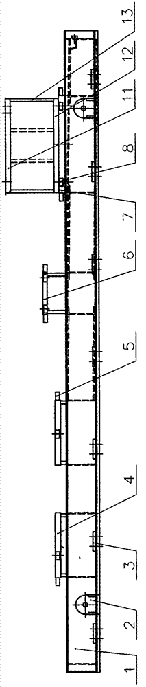
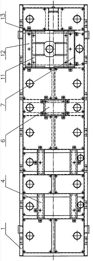
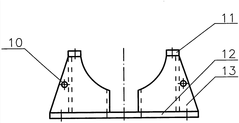
[0011] refer to Figure 1 to Figure 4 As shown, the separate shared pump seat of the multistage centrifugal pump of the present invention includes a chassis 1 (which is a heavy-duty channel steel joint welding method, with a lifting ring 2 and a spacer 3), a motor support plate 4 (and a motor adjustment block 5 ), the transmission equipment support plate 6, the pump base support plate 7 (and the pump base adjustment block 8), the base plate 12 (with detachability) is equipped with the fastener 9 (bolt) on the pump base support plate 7 On the base plate 12, transverse ribs 13 and longitudinal ribs 14 (several strips) are installed, and a pump support block 11 is installed on the top of the transverse ribs 13. The transverse ribs 13 are several and distributed on both sides of the base plate 12, between the transverse ribs and the pump support block are used to support and place the centrifugal pump (its pump body); Lifting holes 10 are provided on the side surfaces of the tran...


PUM


Abstract

The invention discloses a separated shared pump base of a multistage centrifugal pump. The separated shared pump base comprises a base plate (1), a motor support plate (4), a transmission equipment support plate (6) and a pump base support plate (7), wherein a base plate (12) is mounted on the pump base support plate through fasteners (9), transverse rib plates (13) and longitudinal rib plates (14) are mounted on the base plate, and pump support blocks (11) are mounted at the tops of the transverse rib plates. The separated shared pump base has the advantages that during transportation, the centrifugal pump is placed on the pump base, and an extra central support rack is not needed; during maintenance, the whole base plate can be directly separated through lifting, separability and mobility are achieved, base plate cost and simple support cost during transportation are saved effectively, and transportation space occupation and maintenance time occupation are avoided; the pump base is especially suitable for the ultra-large-power centrifugal pump and applicable to the combined welding base plate of the multistage centrifugal pump in the petroleum and petrochemical industries.

Description

technical field [0001] The invention relates to a base used for a multistage centrifugal pump and its unit. Background technique [0002] The centrally supported multistage centrifugal pump is generally a key pump device in the petroleum and petrochemical industries. The size of the whole unit (pump, motor, etc.) is generally about 6 meters long, 2.5 meters wide, about 8 tons in weight, and the price is about 200,000-400,000 yuan. The whole unit is fixed on the heavy-duty channel steel joint welded chassis, and then lifted and transported to the site for installation. The lifting of the whole set of units is easy to bend the heavy-duty channel steel joint welded chassis, causing damage to the unit; taking measures to increase the strength of the welded chassis will waste too much money. Then, in the industry, the pumps and motors of large-scale units are packaged and transported separately, and the small-scale units are transported as a whole. The centrally supported multi...

Claims


Application Information

Patent Timeline
IPC IPC(8): F04D29/00
Inventor 丁江波张伟沈水钦孙森森
Owner ZHEJIANG KEER PUMP
Why Eureka
Try Eureka