Constant-current constant-temperature water mixing valve

A technology of constant temperature mixing valve and warm water outlet, applied in valve device, water treatment site, water/sewage treatment and other directions, can solve problems such as poor accuracy, low outlet water temperature, and no guarantee, and achieve the effect of convenient use

Inactive Publication Date: 2015-08-19
SHANGHAI NICHOLS ELECTRONICS TECH INC
View PDF0 Cites 9 Cited by
  • Summary
  • Abstract
  • Description
  • Claims
  • Application Information

AI Technical Summary

Problems solved by technology

This water mixing process is manually adjusted. This adjustment method has certain defects. The hot water in the inner tank of the water heater will gradually decrease during use, so the temperature of the mixed water will also gradually decrease accordingly. Manually adjust the opening of the hot water and cold water of the mixing valve, but the accuracy of the manual adjustment process is very poor. When the handle is turned too much, the temperature of the mixed water will be high, and when the handle is turned too little, the temperature of the mixed water will be low. The temperature adjustment process is cumbersome; in addition, the mixing valve usually does not have any treatment on the water quality, and there is no guarantee for the water quality used by people. It has become an important requirement in modern life to be able to use healthier water sources. To address the above problems, the existing Those skilled in the art urgently need to provide a constant flow constant temperature water mixing valve, which can not only automatically adjust the outlet water temperature and flow rate, but also purify the water quality

Method used


Image

  • Constant-current constant-temperature water mixing valve
  • Constant-current constant-temperature water mixing valve
  • Constant-current constant-temperature water mixing valve

Examples


Embodiment Construction

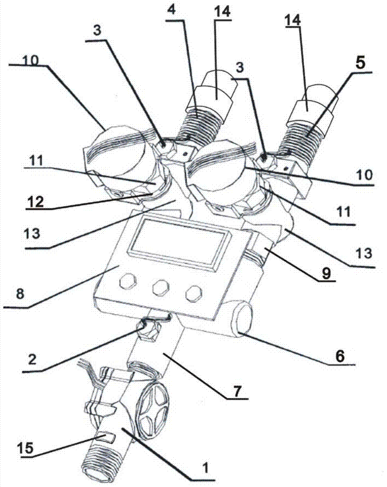
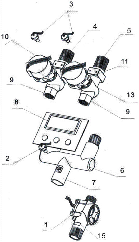
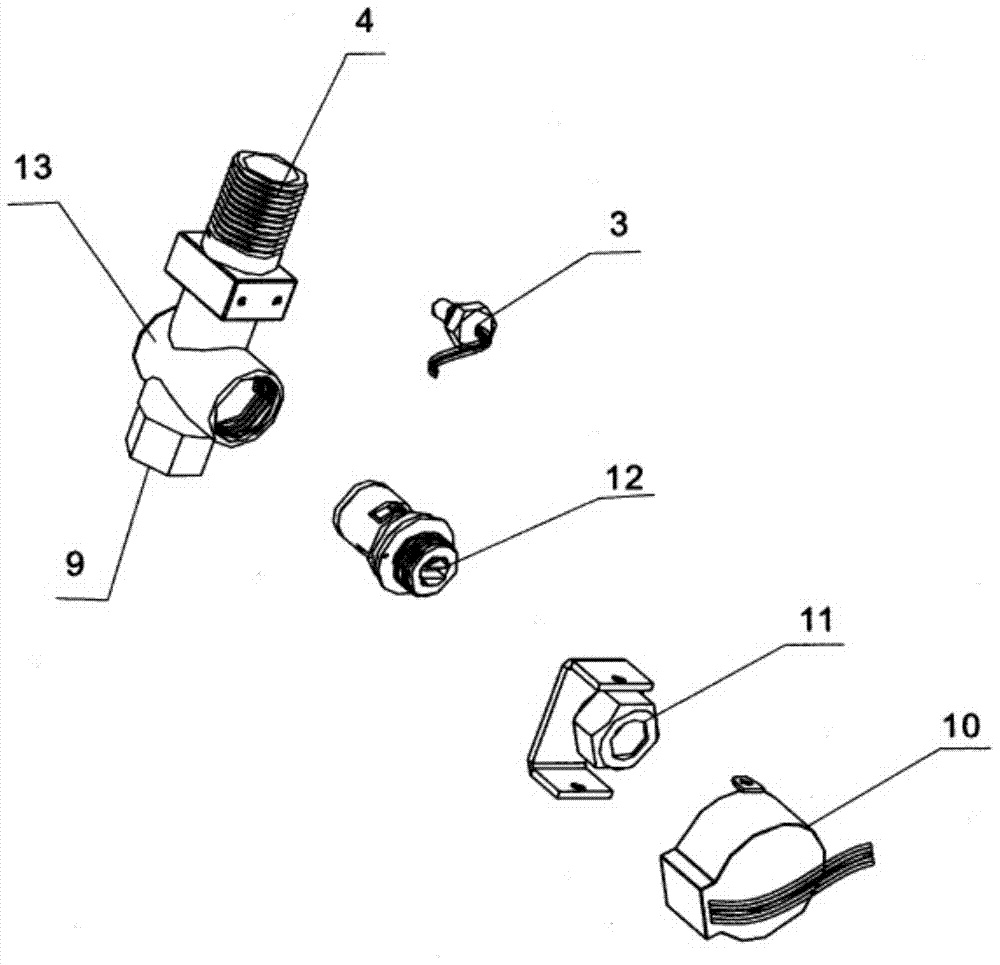
[0018] In order to make the content of the present invention clearer and easier to understand, the content of the present invention will be further described below in conjunction with the accompanying drawings. Of course, the present invention is not limited to this specific embodiment, and general replacements known to those skilled in the art are also covered within the protection scope of the present invention. Secondly, the present invention is described in detail by means of schematic diagrams. When describing the examples of the present invention in detail, for the convenience of explanation, the schematic diagrams are not partially enlarged according to the general scale, which should not be used as a limitation of the present invention.

[0019] The above and other technical features and beneficial effects will be described in detail for the static pressure pipe pile of the present invention in conjunction with embodiments and accompanying drawings. as the picture show...


PUM


Abstract

The invention discloses a constant-current constant-temperature water mixing valve. The water mixing valve comprises a purification device, a hot water inlet, a cold water inlet, a regulating system, a controller, a water mixing slot and a warm water outlet, wherein one end of the hot water inlet and one end of the cold water inlet are respectively connected with the purification device, and the other end of the hot water inlet and the other end of the cold water inlet are respectively connected with one regulating system; first temperature probes for sensing the water flow temperature are respectively arranged at the hot water inlet and the cold water inlet; and a second temperature probe, a water flow detecting device and a water quality detecting device are arranged at the warm water outlet; the controller is used for receiving the data detected by the second temperature probe, the water flow detecting device and the water quality detecting device, and the regulating system and the purification device are controlled to start and stop according to the detected data. According to the water mixing valve, preset water temperature and water flow can be automatically adjusted and cannot be changed along with environmental change; besides the water mixing valve is arranged in the purification device, so that water quality can be effectively purified and a healthy water source can be provided for people.

Description

technical field [0001] The invention relates to the field of control valves. Specifically, the invention relates to a constant-flow and constant-temperature water mixing valve, which is mainly applied to a water outlet of a water heater. Background technique [0002] The constant temperature water heaters sold on the market now adjust the outlet water temperature through the mixing valve. The cold water that is about to enter and the heat in the tank are combined in a certain proportion in the mixing valve to adjust the appropriate outlet water temperature. This water mixing process is manually adjusted. This adjustment method has certain defects. The hot water in the inner tank of the water heater will gradually decrease during use, so the temperature of the mixed water will also gradually decrease accordingly. Manually adjust the opening of the hot water and cold water of the mixing valve, but the accuracy of the manual adjustment process is very poor. When the handle is t...

Claims


Application Information

Patent Timeline
Patent Type & Authority Applications(China)
IPC IPC(8): F16K37/00C02F1/28
CPCF16K37/0091C02F1/283C02F2003/003C02F2307/12
Inventor 陈金恩李文先苑红辉
Owner SHANGHAI NICHOLS ELECTRONICS TECH INC
Why Eureka
Try Eureka