Device for testing underground space spallation strength and application thereof

A technology of underground space and testing equipment, applied in the direction of measuring equipment, strength characteristics, instruments, etc., can solve the stress situation that cannot accurately reflect the damage of spalling, and there is no testing method and device that considers the strength of spalling. Accurately obtain spalling strength and other issues

Inactive Publication Date: 2015-08-19
CENT SOUTH UNIV
View PDF6 Cites 16 Cited by
  • Summary
  • Abstract
  • Description
  • Claims
  • Application Information

AI Technical Summary

Problems solved by technology

Obviously, these two devices have obvious defects when measuring the spalling strength of the surface of the underground space, and neither can accurately reflect the force of spalling damage in the surrounding rocks of the underground chamber, so that the spalling strength cannot be accurately obtained
[0005] So far, there is no test method and device for the spalling strength of the underground space surface considering the confining pressure and axial pressure

Method used


Image

  • Device for testing underground space spallation strength and application thereof
  • Device for testing underground space spallation strength and application thereof
  • Device for testing underground space spallation strength and application thereof

Examples


Embodiment 1

[0085] In this embodiment, the diameters of the incident rod, the sample, and the transmission rod are equal, wherein the size of the incident rod is Φ50×2000 mm, and the size of the transmission rod is Φ50×1500 mm;

[0086] step one

[0087] Measure sample density ρ=2740kg / m 3 Finally, according to the designed size, it is processed into a cylindrical sample 7; the end of one end of the sample 7 is provided with a U-shaped groove; the length of the sample 7 is 20cm; the two ends of the cylindrical sample 7 and the test piece The surface of the sample is polished flat and smooth so that the unevenness is less than 0.02mm, so as to reduce the distortion and dispersion effect generated by the stress wave in the process of propagating inside the sample 7; the size of the U-shaped groove is , and the width B of the notch is 3cm , the groove depth H is 6cm;

[0088] step two

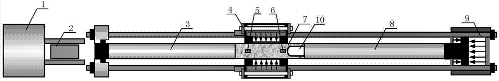
[0089] Air gun 1, punch 2, incident rod 3, confining pressure providing device 4, first set of strain g...

Embodiment 2

[0110] In this embodiment, the diameters of the incident rod, the sample, and the transmission rod are equal, wherein the size of the incident rod is Φ50×2000 mm, and the size of the projection rod is Φ50×1500 mm;

[0111] Step A

[0112] After measuring the rock density ρ=2740, according to the designed size, it is processed into a cylindrical sample 7; the end of one end of the sample 7 is provided with a U-shaped groove; the length of the sample 7 is 20cm; The two ends of sample 7 and the surface of the sample are ground flat and smooth so that the unevenness is less than 0.02 mm, so as to reduce the distortion and dispersion effect produced by the stress wave in the process of propagating inside the sample 7; the size of the U-shaped groove is, The slot width B is 3cm, and the slot depth H is 6cm;

[0113] Step B

[0114] Air gun 1, punch 2, incident rod 3, confining pressure providing device 4, first set of strain gauges 5, second set of strain gauges 6, transmission ro...


PUM

PropertyMeasurementUnit
lengthaaaaaaaaaa
densityaaaaaaaaaa
lengthaaaaaaaaaa

Abstract

The invention relates to a device for testing spallation strength and application thereof, in particular to a device for testing underground space spallation strength and application thereof. The testing device designed by the invention comprises an air gun (1), a punch head (2), an incident bar (3), a confining pressure providing device (4), a first group of strain gages (5), a second group of strain gages (6), a test sample (7), a transmission bar (8) and an axial pressure providing device (9), wherein one end of the test sample (7) is provided with a groove (10). Since the test sample is simple to prepare and the initial stress of the material is easy to add, the device for testing underground space spallation strength has the advantages of simplicity and quickness in measurement operation, high practicability, high result reliability and the like.

Description

technical field [0001] The invention relates to a test device for spallation strength and the application of the device; in particular, it relates to a test device for the spallation strength of the surface of an underground space and the application of the device. technical background [0002] As early as 1914, Hopkinson (Hopkinson) proposed the dynamic mechanical performance testing method of materials under high-speed loading conditions. At present, there are many methods for measuring the spallation strength of brittle materials such as rocks based on the Hopkinson compression bar test device under the condition of no initial stress, such as the spallation block velocity method and the pull-back velocity method. The spallation block velocity method uses The relationship between the stress at a certain point in the sample and the particle velocity is σ=ρCV, and the spallation strength of the sample is calculated by measuring the shedding speed of the layer crack block, wh...

Claims


Application Information

Patent Timeline
Patent Type & Authority Applications(China)
IPC IPC(8): G01N3/307
Inventor 陶明李夕兵曹文卓褚夫蛟杨伟蒋海波
Owner CENT SOUTH UNIV
Why Eureka
Try Eureka